OPTION 008 RF PROFILES AND COMPLEX SWEEP
Annex-C-10
Carrier :
Freq.
RF Level : dBm
Single Modulation Mode Modulation ENABLED
MHz
Int Std: 10 MHzOffset: +20 dB Profile 1
FM: Hz
Int F4: 1.0000 kHz
0
ON
100.000 0000
+0.0
ON
FM
Devn.
Source
Freq : F4
FM
ON/OFF
Select
Source
RF
Level
Carrier
Freq.
LOCAL
Low
Intermod
ΦM
AM
Wideband
FM
C0867
Fig. C-7 Main signal generator screen with RF offset and profiles enabled
Tutorial examples for RF offset and profiles
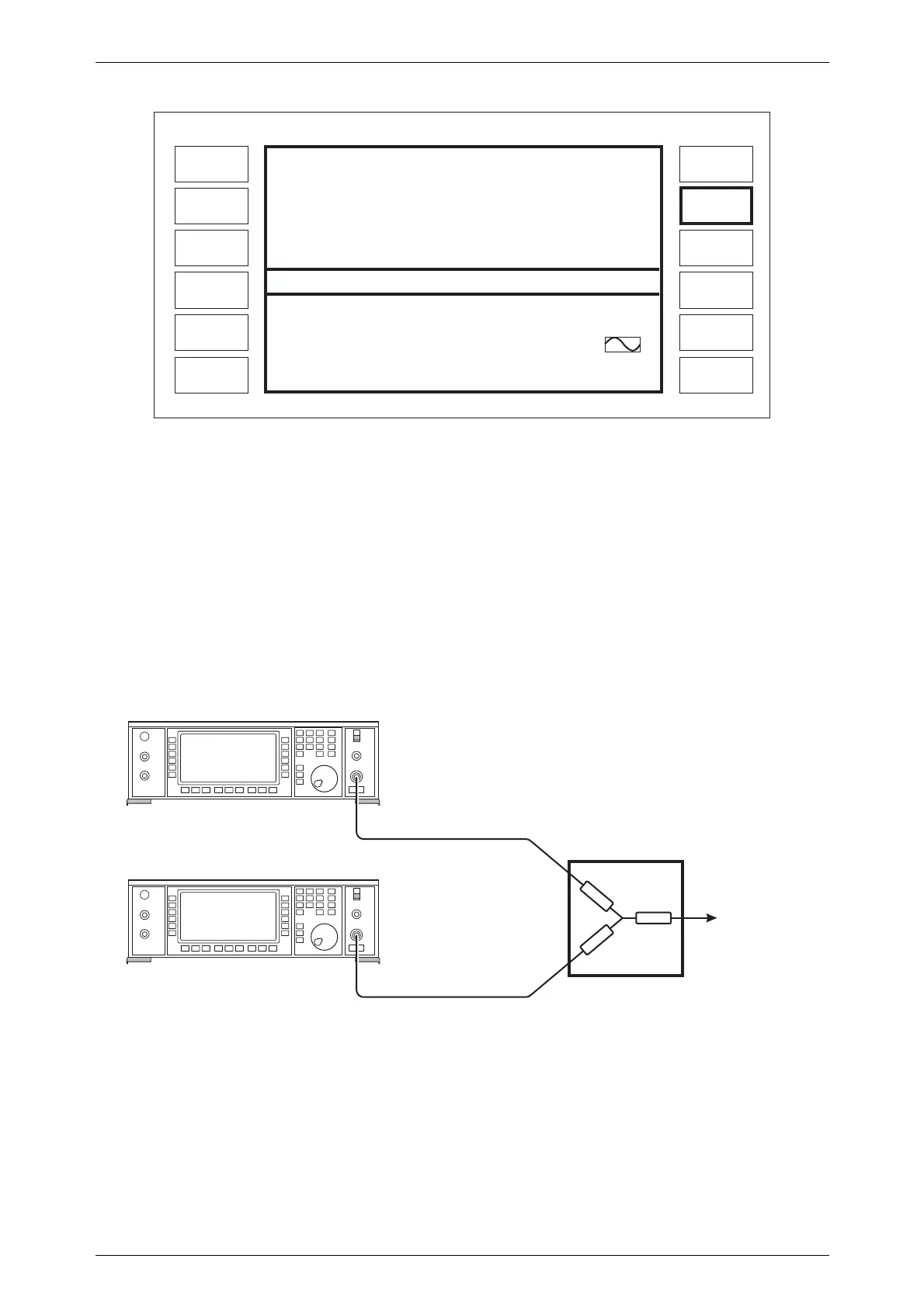
Example 1: RF offset - compensating for a combiner
Problem:
An application requires the addition of two RF signals with a combiner as shown in Fig.
C-8. The combiner has 6 dB insertion loss and it is desirable for the signal generators to display
the signal level after the combiner.
C0868
RF OUTPUT
TO
UNIT
UNDER TEST
RF OUTPUT
2030/40 Series
SIGNAL GENERATOR
2030/40 Series
SIGNAL GENERATOR
COMBINER
Fig. C-8 Two signal generator testing with a resistive combiner

 Loading...