OPTION 008 RF PROFILES AND COMPLEX SWEEP
Annex-C-11
Solution:
Use the RF offset facility. Set the RF output level (for example to +6 dBm). Then set
Offset 1 (see Fig. C-3) to -6 dB and enable the offset. The signal generators provide
outputs of +6 dBm to compensate for the signal loss of the combiner whilst now
displaying the signal level after the combiner (in the example 0 dBm) as required.
Note that the maximum displayed RF level will now be limited to +7 dBm since this
represents +13 dBm at the RF output connector (unless the overrange facility is enabled).
If the save setting facility is used (Fig. C-3) the generator can be set so that every time it
is switched on a -6 dB offset is applied.
Example 2: RF offset and profiles - compensating for an amplifier
Problem:
The signal generator is being used with an external amplifier having a nominal gain of
28 dB. The generator is being used over the frequency range 100 MHz to 500 MHz.
Amplifier frequency response and cable losses result in the overall gain of the amplifier
system varying between 25 dB and 31 dB. The signal generator is required to display the
power at the output of the amplifier.
Solution:
Use both RF offset and RF profile. First use the RF offset facility to enter an offset value
of 28 dB (i.e. the mid-point of 25 and 31 dB). Connect a power meter to the amplifier as
shown in Fig. C-9 after making sure that the amplifier output is at a level which will not
damage the power meter.
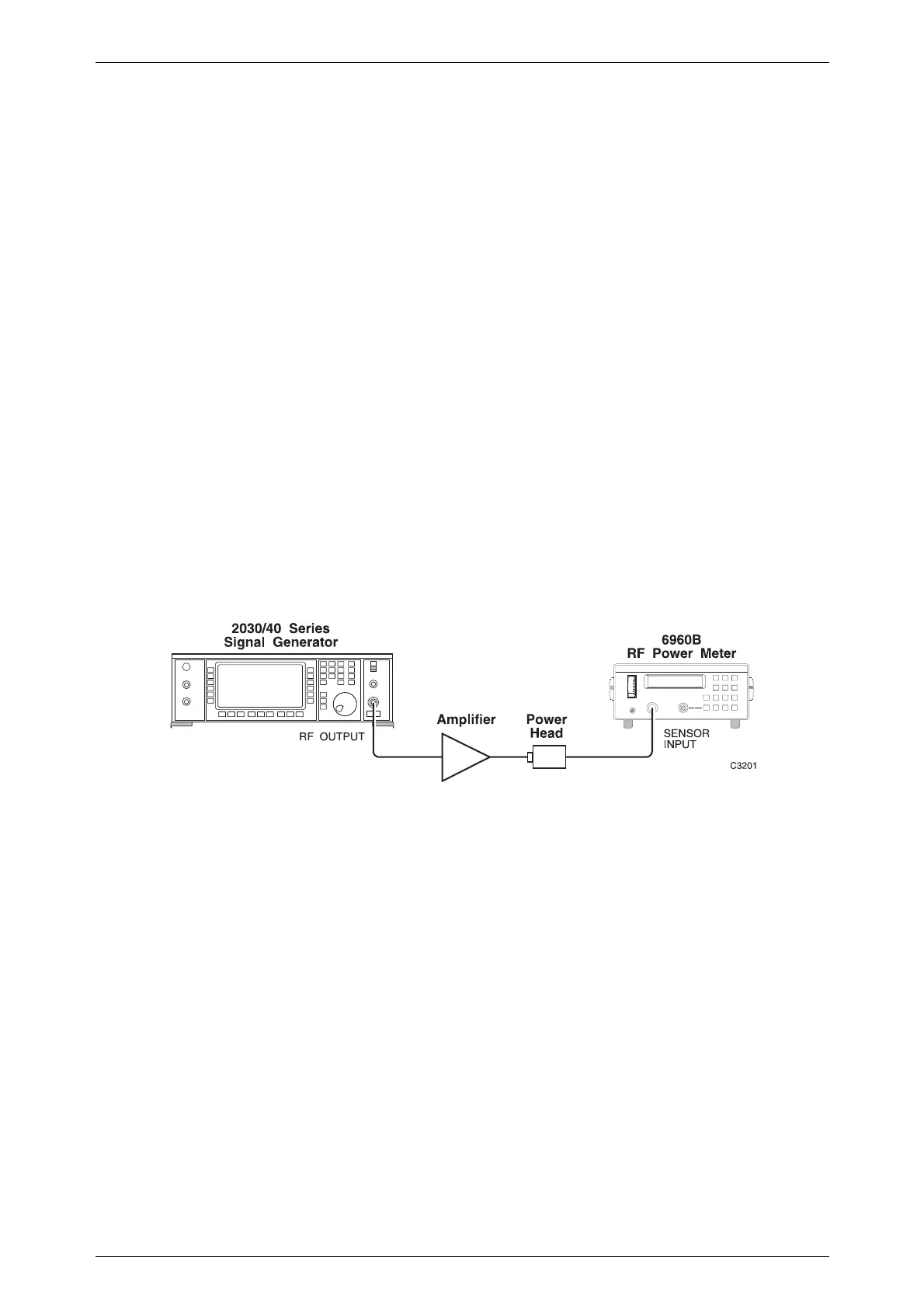
Fig. C-9 Using a signal generator with an external amplifier
A profile can now be added to reduce the frequency dependent RF level errors. With the
signal generator level set at (for example) 0 dBm and unlocked to Level 1, select the RF Profile
Editor shown in Fig. C-6.
Enter a carrier frequency of 100 MHz. Adjust the Profile Level until the power meter
reads 0 dBm and then save the point. Repeat for carrier frequencies of 150 MHz, 200 MHz,
250 MHz, 300 MHz, 350 MHz, 400 MHz, 450 MHz and 500 MHz. The profile will now have 9
calibration points entered.
Use the [Store Profile] key to store as Profile 0. Exit to the RF Profile Menu and select
and enable Profile 0.
Press the [SIG GEN] key to obtain the main Sig Gen menu. Use the rotary control to vary
the carrier frequency between 100 MHz and 500 MHz and check that the power meter reading is
acceptably close to 0 dBm. Extra points can be added to the profile if required to reduce errors at
intermediate frequencies.

 Loading...