ACCEPTANCE TESTING
5-1-D-2
TEST PROCEDURES
Before each test, it is recommended that the UUT is reset to its switch-on conditions
which are as follows:
Carrier freq 1.35 GHz (2030), 2.7 GHz (2031)
RF level −138 dBm
FM 0 Hz ON
Single modulation mode
Modulation ENABLED
RF OUTPUT
SPECIFICATION
Level range: -127 dBm to +10 dBm (usable to -138 dBm)
Accuracy: (2030 and 2031)
±1.2 dB from 10 kHz to 1.35 GHz at levels >-127 dBm
(2031)
±1.2 dB from 1.35 GHz to 2.7 GHz at levels >-127 dBm
TEST EQUIPMENT
Description Minimum specification Example
RF power meter ±0.1 dB from 30 kHz to 2.7 GHz IFR 6960B and 6910 or 6912
sensor
Measuring receiver 0 dBm to −127 dBm; 2.5 MHz to
1300 MHz
HP 8902A and 11722A
sensor and 11793A
down converter
Signal generator 8 dBm from 32.5 MHz to 5.4 GHz IFR 2032
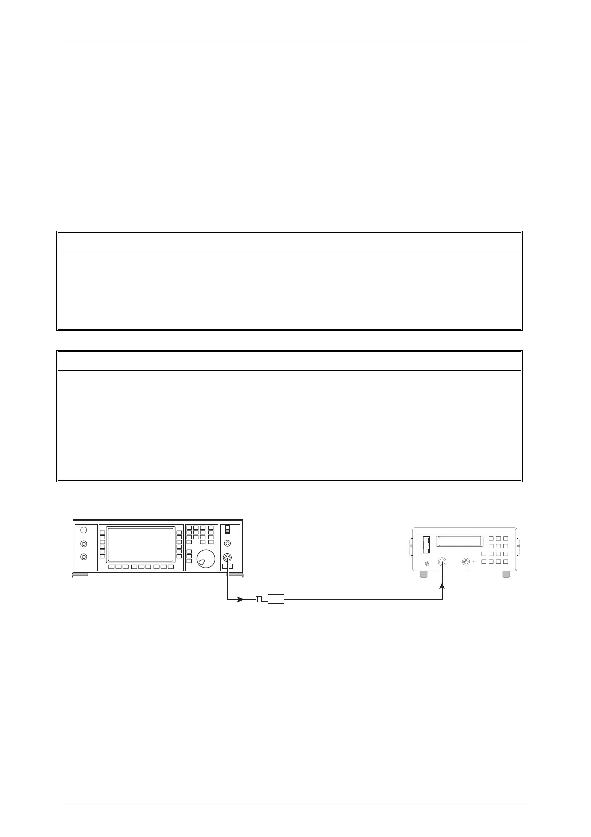
Fig. 5-1-D-1 RF output flatness test set-up
(1) Connect the test equipment as shown in Fig. 5-1-D-1.
(2) Set the UUT to [RF level] 0 dBm, [Carrier freq.] 250 kHz.
(3) Check that the output level is within specification at the frequencies shown in
Table 5-1-D-1.
(4) Set the UUT RF output to 10 dBm and repeat (3) above.
TEST PROCEDURES
C3192
RF OUTPUT
6910
or
6912
Power
Sensor
UUT
6960B
RF Power Meter
SENSOR
INPUT

 Loading...