OPTION 006 Avionics
Annex-B-11
Communication channel testing is normally only required on localiser frequencies and
consequently changing from localiser to glideslope using the [LOC/GS Freq.] key will result in
the [Ident/Comms] key disappearing. Additional modulation can be obtained on a glideslope
frequency by directly entering the glideslope frequency instead using the numeric keys.
Tone phase variability
For normal ILS operation the phase setting between the 90 Hz and 150 Hz tones is
automatically set to 0°. The [90/150 Phase] key can be used to adjust the phase relationship of
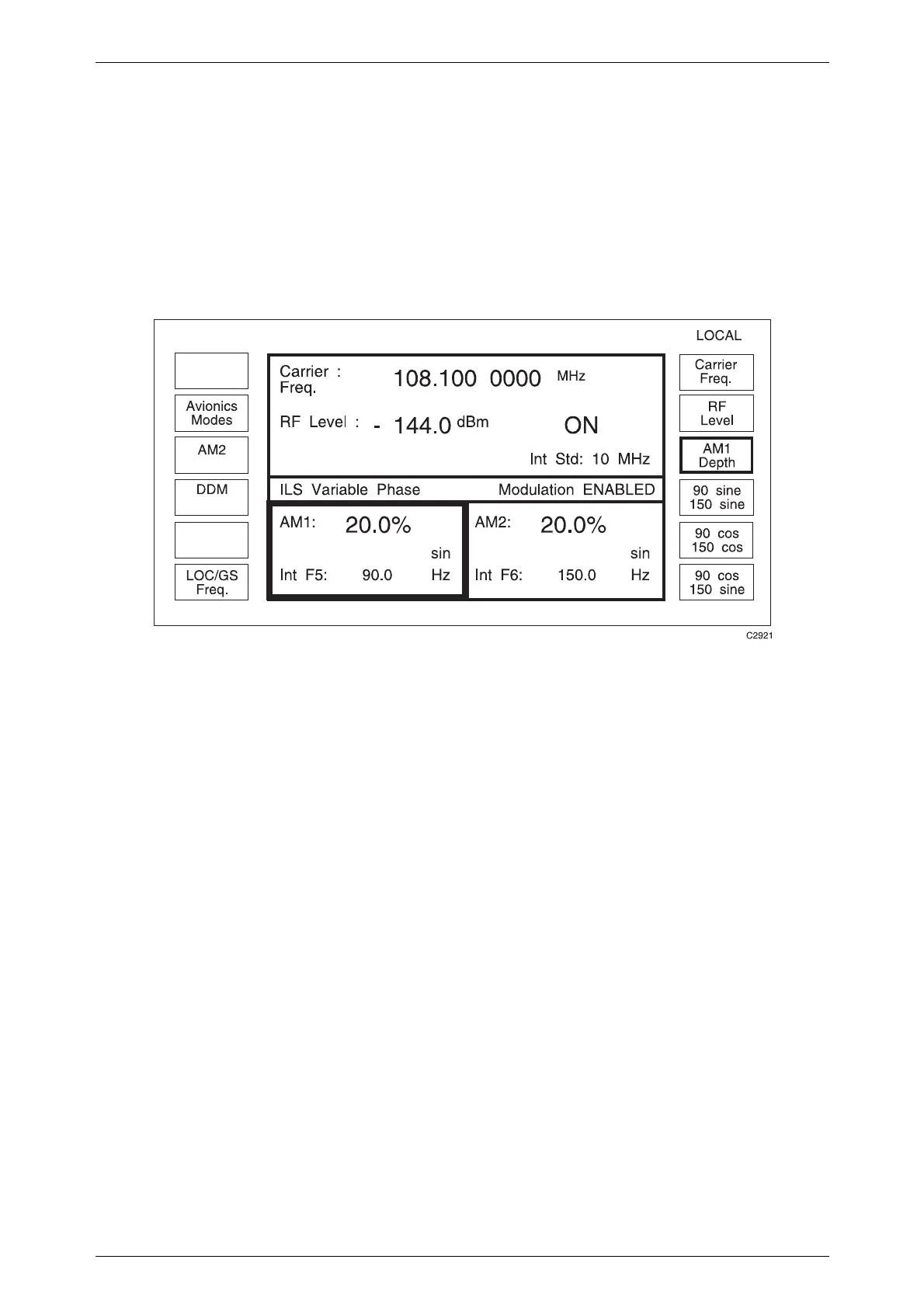
the two tones. Selecting the [90/150 Phase] key produces the display shown in Fig. B-9.
Fig. B-9 ILS variable phase sub-menu
Three phase relationships can be selected:
90 Hz sine/150 Hz sine
90 Hz cosine/150 Hz cosine
90 Hz sine/150 Hz cosine (≡ 90 Hz cosine/150 Hz sine)
Selecting [DDM] will return the instrument to normal ILS mode.
Marker beacon mode
The marker beacon mode is selected using the [MARKER BEACONS] key on the
Avionics Mode Selection menu shown in Fig. B-3. Selecting maker beacon mode and pressing
the [SIG GEN] key produces the display shown in Fig. B-10. Initially the outer beacon is
selected by default. The [Middle Beacon] and [Inner Beacon] keys change the modulation
frequency to 1.3 kHz and 3 kHz respectively. Carrier frequency and AM depth can be altered,
but always default to 75 MHz and 95% respectively. Modulation frequency can be changed
using the [Source Freq: F1] key. Modulation source can be changed using the [Select Source]
key. Pressing the [Avionics Modes] key returns the display to the Avionics Mode Selection
menu.

 Loading...