OPTION 009 PULSE GENERATOR
Annex-D-6
(20) VIDEO 50 Ω BNC socket provides the video output signal of the internal
pulse generator. When used for pulse modulation, this signal is
synchronous with the RF pulse:TTL.
(12) SYNC 50 Ω BNC socket supplies the sync signal which indicates the start
of the video signal:TTL, 400 ns wide.
Operation
Connections are made to the instrument via three BNC sockets. External trigger or
external pulse sources are applied to PULSE INPUT on the front panel, a 400 ns synchronisation
pulse is available at SYNC on the back panel and a video signal is available at VIDEO on the
back panel. It is recommended that double-screened cables are used to/from these connectors.
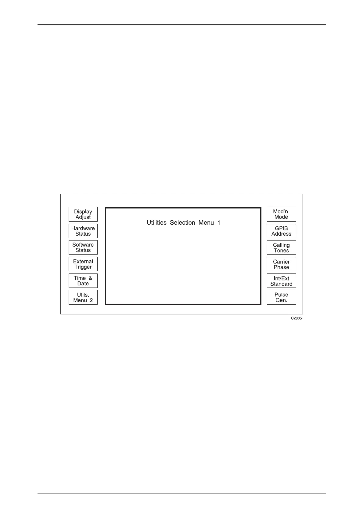
The usual method of accessing the pulse generator configuration menu is by pressing the
[UTIL] key and pressing the [Pulse Gen.] key on the Utilities Selection Menu 1, as shown in
Fig. D-8.
Fig. D-8 Utilities selection menu 1
If the pulse modulator Option 002 is fitted, a [Pulse Mod.] soft key becomes available on
the main [SIG GEN] screen. Pressing this soft key followed by [Pulse Config.] brings up the
same pulse generator configuration menu.
Figure D-9 shows the menu with no pulse modulator fitted (or pulse modulator fitted, but
with the 2030 in a different modulation mode, e.g. AM).

 Loading...