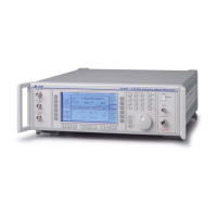
OPTION 008 RF PROFILES AND COMPLEX SWEEP
Annex-C-2
PERFORMANCE DATA
General description
Option 008 software provides additional sweep, RF offset and RF level profiling facilities
to support the use of 2030 series Signal Generators with external amplifiers and attenuators. The
RF output from the external device can be calibrated and displayed on the front panel of the
signal generator using the RF offset and RF profile facilities.
The following specification is in addition to the specification for the 2030 series Signal
Generators.
RF OFFSETS
The displayed signal generator output level can be offset
by +80 dB to −40 dB (in 0.1 dB steps) from the actual
RF output level. Up to 5 offsets values may be defined
and selected in turn.
RF offsets can be enabled and disabled and their value
and status stored in non-volatile memory. RF offsets
may be used in normal signal generator modes or
combined with the segmented sweep facility.
RF PROFILE
The actual RF output level can be adjusted by ±40 dB
from its nominal value without changing the displayed
level. Up to 10 profiles may be defined and selected in
turn. RF profiles can be enabled and disabled and all RF
profile information can be stored in non-volatile
memory.
Profile values can be entered at up to 100 carrier
frequencies.
The RF output level is linearly interpolated between
profile points.
RF profiles may be used in normal signal generator
modes or combined with the segmented sweep facility to
produce complex sweeps.
SEGMENTED SWEEP
Carrier frequency sweeps can be generated which
contain defined segm
ents each of which can have a
different step size, start and stop frequency, step time and
RF level.
Start and stop Start and stop frequency for each segment can be freely
defined within the frequency capability of the signal
generator.
Step size Minimum step size is 0.1 Hz.
Maximum step size is determined by the frequency
capability of the signal generator.
Number of steps for a particular segment is implied by
the step size and the start and stop frequencies.

 Loading...