OPTION 010 DME Modulator
Annex-E-15
DME pulse modulator
TEST EQUIPMENT
Description Minimum specification Example
Spectrum analyser DC to 1.5 GHz
3 MHz resolution bandwith
3 MHz video filter
10 μs sweep time (zero span)
IFR 2392
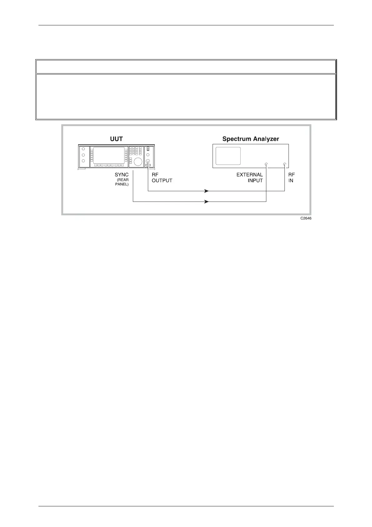
Fig. E-14 Pulse modulator functional test set-up
(1) Connect the test equipment as shown in Fig. E-14.
(2)
RF linearity
Set up the equipment as follows:
Unit under test:
Modulation mode Avionics, DME
RF level 0 dBm
Spectrum analyser:
Centre frequency 1025 MHz
Span 0 Hz
Ref level 0 dBm
Resolution bandwidth ≥ 3 MHz (30 MHz, 2392)
Video bandwidth ≥ 3 MHz (NONE, 2392)
Sweep time 1 µs/div
Trigger mode External
Vertical scale Linear
The analyser should display a characteristically gaussian shaped pulse, width
3.5 µs, rise and fall times 2.5 µs. If the analyser has no external trigger facility,
trigger mode should be set to VIDEO.
(3)
Level accuracy
With the equipment otherwise set up as in the previous test, set the sweep to
2 µs/div, and the vertical scale to logarithmic, 1 dB/div. The peaks of the two
pulses should have a nominal level of 0 dBm, and both peaks should have the
same amplitude (±0.5 dB). This should remain the case when the RF level is
increased or decreased.

 Loading...