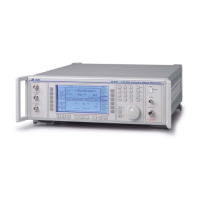
OPTION 008 RF PROFILES AND COMPLEX SWEEP
Annex-C-4
INTRODUCTION TO OPTION 008
This section describes how to use the additional software features provided when
Option 008 RF profile and complex sweep is fitted to a 2030 series Signal Generator. Familiarity
with normal operation of the signal generator is assumed.
Option 008 provides two principle facilities. The RF offset facility enables the user to
effectively display the RF output level when the signal generator is connected to an external
device, such as an attenuator or an amplifier. If the external device gain or loss is frequency
dependent then the signal generator can substantially eliminate the frequency dependence using
RF profiles.
The segmented sweep facility allows for the generation of sweeps where the sweep is
split into segments which can have independent start, stop, step size, step time and RF levels.
The complex sweeps are generated using the segmented sweep mode and can be used in
combination with the RF profile and RF offset facility. This is particularly useful for
electromagnetic immunity and Tempest testing.
Complex sweeps can be generated by combining the RF offset, RF profile and segmented
sweep facilities.
RF OFFSET AND PROFILES
These facilities provide the capability for setting the signal generator to display the RF
power at the output of a device connected to the signal generator. The RF offset facility is used
to compensate for the nominal gain (or loss) of the external device. Adding an offset value does
not change the RF output level of the signal generator but does change the displayed RF output
level. If, for example, the signal generator is connected to a 20 dB amplifier the offset value can
be set to +20 dB. If the signal generator output level is set to +20 dBm then +20 dBm is
displayed but the actual signal generator output level will be 0 dBm.
The RF profile facility allows the output level to be corrected to allow for frequency
dependent gain (or loss) errors. If, for example, the gain of the amplifier at 100 MHz is 20 dB, at
150 MHz it is 19 dB and at 200 MHz it is 19.5 dB the RF profile facility can introduce 0 dB,
1 dB and 0.5 dB level compensation at 100 MHz, 150 MHz and 200 MHz respectively to
compensate for the frequency/gain errors. The RF level profile is linearly interpolated between
these frequencies to minimise level errors at intermediate frequencies.
The profile values do not change the displayed RF level but do change the RF output
level of the signal generator.
Access to RF offset and profile
The RF offsets and profiles are initially accessed via the Utilities Selection Menu 2. To
obtain this menu, press [UTIL]. If the Utilities Selection Menu 1 is displayed, press the [Utils.
Menu 2] key. The required display is shown in Figure C-1.
Note...
If the utility facility has already been previously accessed it may be necessary to press the
[UTIL] key a second time and then select [Utils Menu 2].

 Loading...