INSTALLATION
2-7
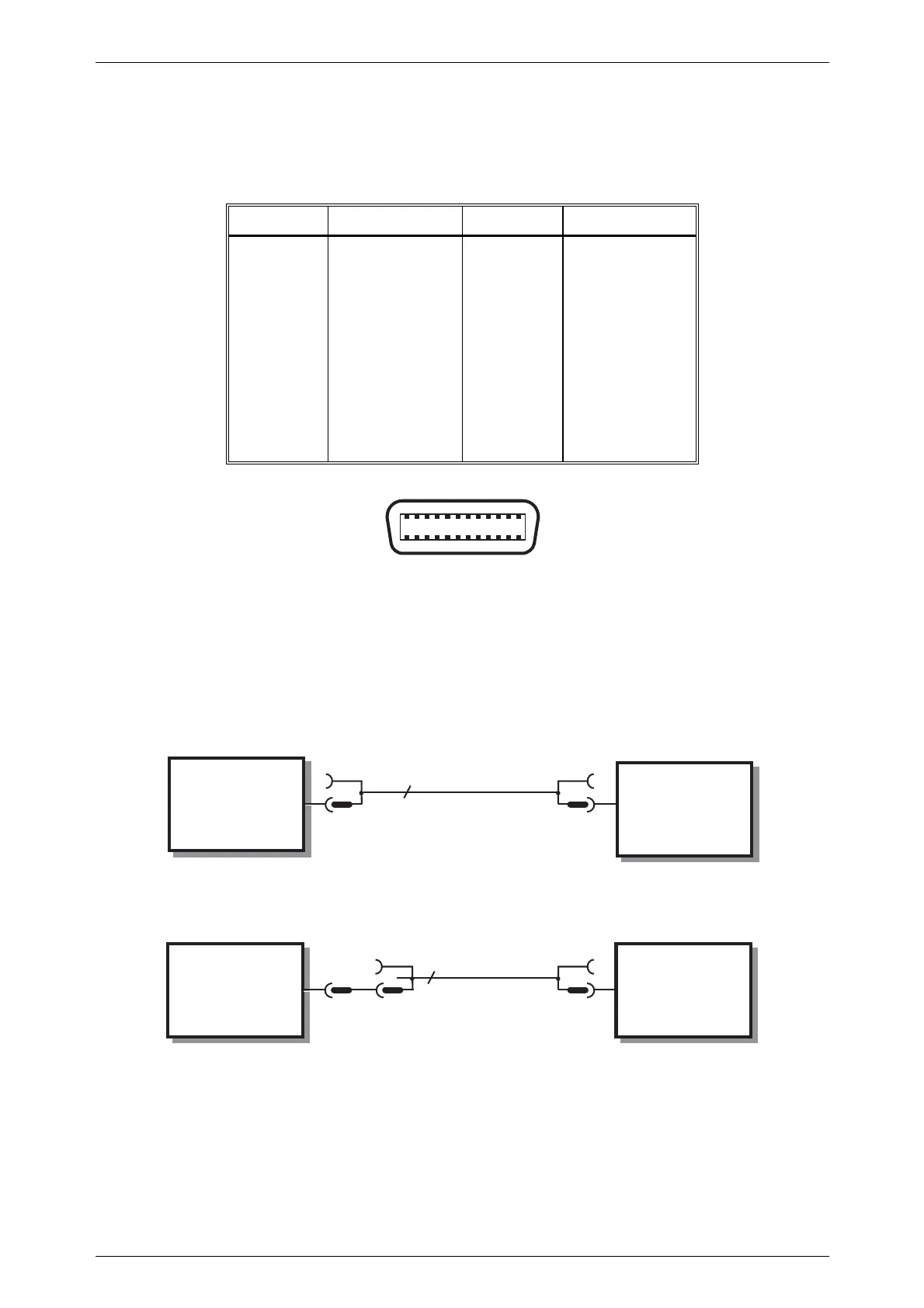
GPIB connector contact assignments
The contact assignments of the GPIB cable connector and the device connector are as
shown in Fig. 2-2.
Contact Function Contact Function
1
2
3
4
5
6
7
8
9
10
11
12
Data I/O 1
Data I/O 2
Data I/O 3
Data I/O 4
EOI
DAV
NRFD
NDAC
IFC
SRQ
ATN
Ground shield
13
14
15
16
17
18
19
20
21
22
23
24
DataI/O 5
DataI/O 6
DataI/O 7
DataI/O 8
REN
Pair with 6
Pair with 7
Pair with 8
Pair with 9
Pair with 10
Pair with 11
Logic ground
12 1
24 13
Fig. 2-2 GPIB connector contact assignments (viewed from rear of instrument)
IEEE to IEC conversion
An optional IEEE to IEC adapter is also available (see Chap. 1 'Optional Accessories') for
interfacing with systems using a 25-way bus connector to IEC Recommendation 625. The
method of use is shown in Fig. 2-3.
Fig. 2-3 IEEE to IEC conversion
INSTRUMENT
(IEE
CONNECTOR)
EQUIPMENT
WITH IEEE
CONNECTOR
INSTRUMENT
(IEE
CONNECTOR)
EQUIPMENT
WITH IEC
CONNECTOR
24
25
IEEE LEAD
IEEE to IEC
ADAPTER
IEC LEAD
46883-408K
C0032

 Loading...