OPTION 009 PULSE GENERATOR
Annex-D-5
PULSE GENERATOR OPERATION
Introduction
This section explains how to use Option 009 when fitted to a 2030 Signal Generator.
Familiarity with the normal operation of the instrument is assumed.
Note...
When connecting the VIDEO and/or PULSE INPUT connectors to external equipment, a
double-screened coaxial cable should be used in order for the instrument to conform to EMC
requirements.
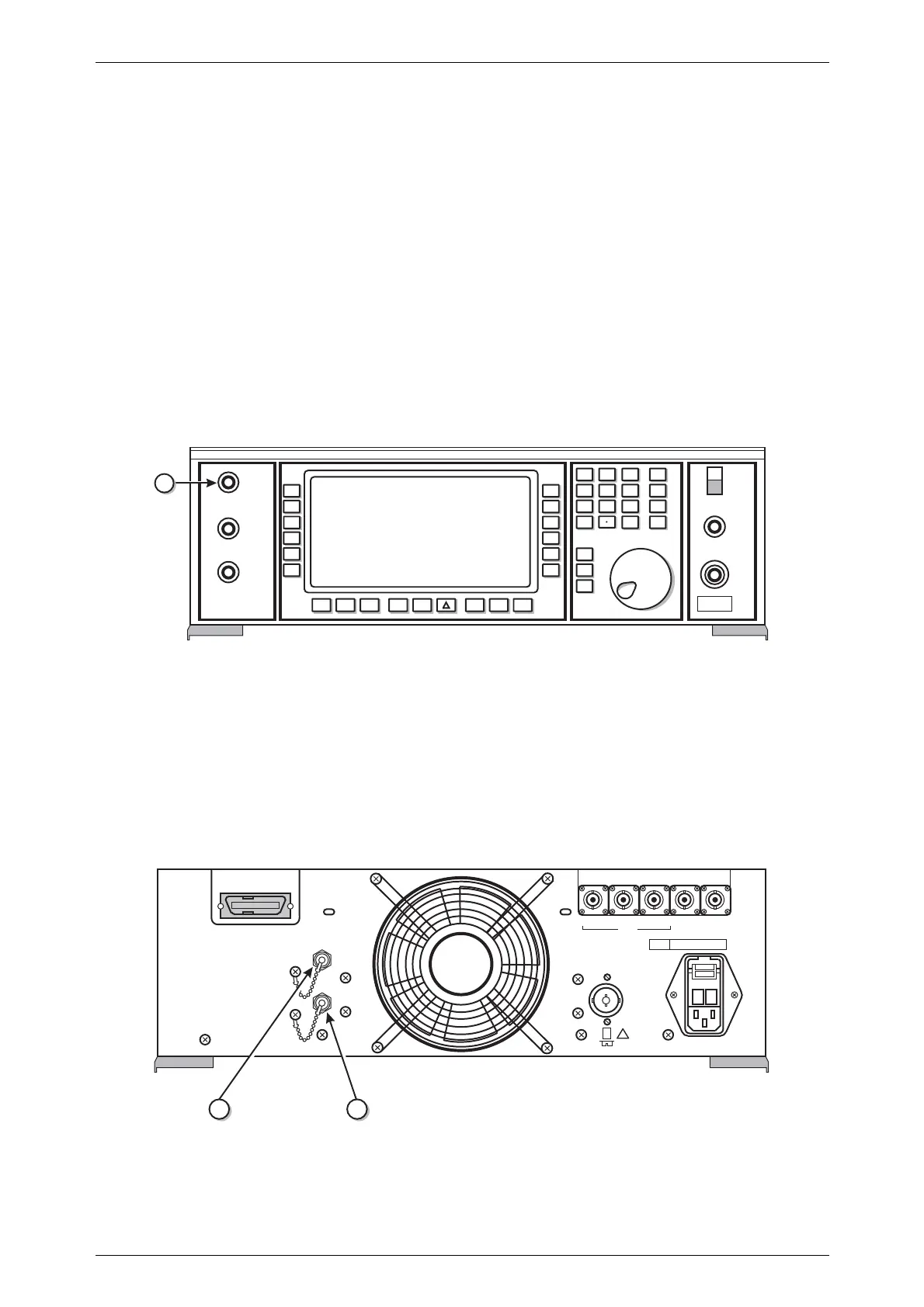
Front panel
The front panel of the instrument fitted with Option 009 differs from the basic instrument
as follows:
REVERSE POWER
50W MAX
PULSE INPUT
50
W
50
W
EXT MOD 1
INPUT
EXT MOD 2
INPUT
W
100 k
W
100 k
0
-
MOD
ON-OFF
LF
ON-OFF
UTIL
MEM LF SWEEP
SIG GEN
x10
10
¸
SUPPLY
LF
OUTPUT
RF OUTPUT
enter
ms
%
rad
Hz
dB
3
é
é
7
8
GHz
V
4
5 6
MHz
mV
1 2
kHz
V
m
C5713
CARR
ON-OFF
KNOB
UP-ON
9
10kHz-2.7GHz signal generator 2031
20
O
I
Fig. D-6 2031 front panel with Option 009
(20) PULSE INPUT 50 Ω BNC socket accepts a pulsed signal to trigger the pulse
generator or to directly control the pulse modulator (Option
002):TTL.
Rear panel
The rear panel of the instrument fitted with Option 009 differs from the basic instrument
as follows:
C5714
1211
îî
220Vac
240Vac
~
~
+
_
MARKER RAMP
SWEEP
TRIGGER
WIDE BAND
FM IN
FREQ STD
IN/OUT
GPIB
VIDEO
SYNC
SH1 AH1 SR1 RL1 DC1 DT1
T6 L4 E2 C0 PP0
------------
------------
FUSE
RATING
100/120V~ TT1.6AL250V
220/240V~ TT1AL250V
POWER SUPPLY
100/120/220/240V~
50-400Hz
180VA MAX
!
Fig. D-7 2031 rear panel with Option 009

 Loading...