OPTION 005 GMSK Bt 0.3
Annex A-8
REAR PANEL
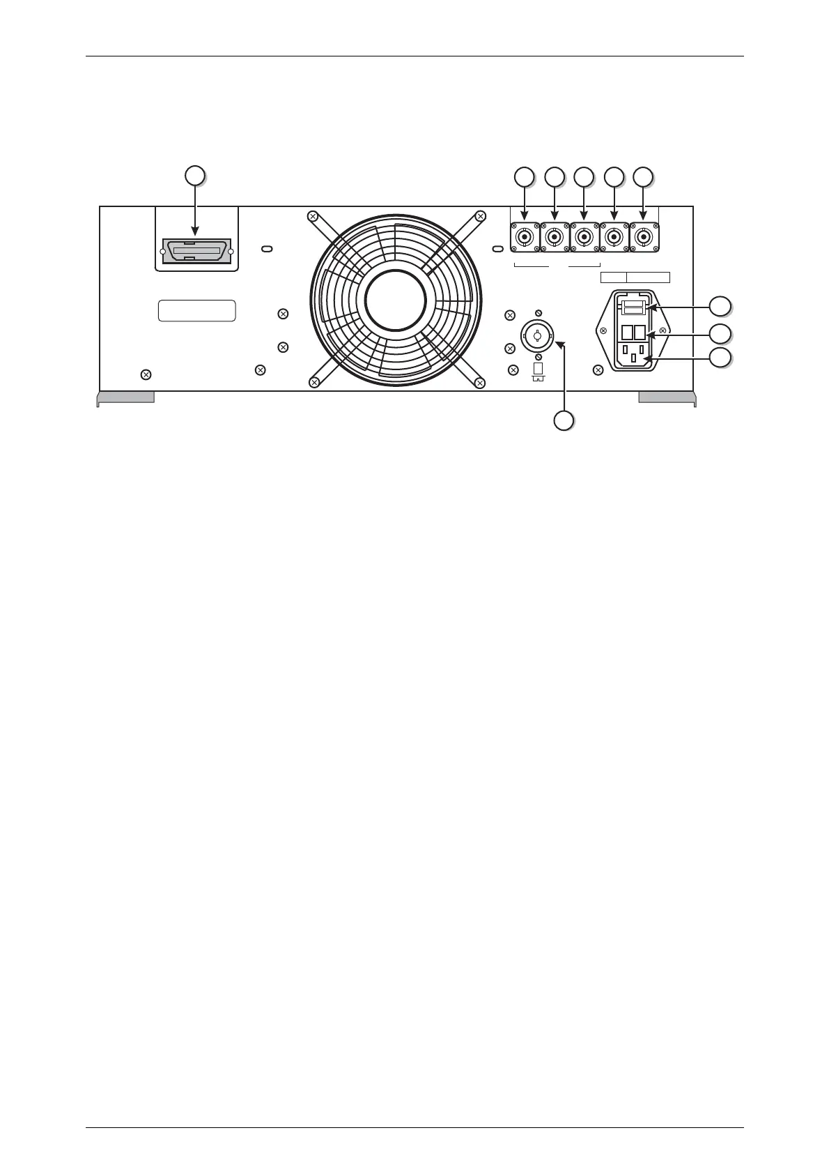
The following facilities are available on the rear panel, see Fig. A-2.
C0398
10
3562
1
4
➮➮
220Vac
240Vac
~
~
9
8
7
+
_
FUSE
RATING
100/120-1.6A-TT
220/240-1A-TT
MARKER RAMP
SWEEP
TRIGGER
SYNC
WIDE BAND
FM IN
DOPPLER
FREQ STD
IN/OUT
POWER SUPPLY
50-400Hz 120VA
100V SET
120V SET
220V SET
240V SET
90-115V
105-132V
188-242V
216-265V
GPIB
SH1 AH1 SR1 RL1 DC1 DT1
T6 L4 E2 C0 PP0
------------
------------
Fig. A-2 2031 rear panel with Option 005
(1) GPIB 24 pin socket accepts standard IEEE connector to allow remote
control of the instrument.
(2) SWEEP MARKER BNC socket supplies sweep marker.
(3) SWEEP RAMP BNC socket provides a ramp output at 0 to 10 V peak-to-peak.
(4) SWEEP TRIGGER
or SYNC
BNC socket provides access for a trigger input or SYNC
input/output in GSM Mode.
(5) WIDE BAND
FM IN or
DOPPLER
BNC socket accepts a wide bandwidth FM signal into 50 Ω with
a typical bandwidth of 10 MHz. In GSM mode the connector
may be used for Doppler simulation.
(6) FREQ STD
IN/OUT
BNC socket for standard frequencies at 1, 5 or 10 MHz with a
nominal 2 V pk-pk level into 50 Ω. In GSM mode an additional
standard of 13 MHz can be accepted and generated.
(7) VOLTAGE
SELECTOR
Removable cover reveals barrel which can be rotated to select the
required voltage range.
(8) FUSES AC fuses rated at 1.6 A TT (double time lag) for the 100 to 120 V
range and 1 A TT (double time lag) for the 220 to 240 V range.
(9) AC SUPPLY INPUT 3 pin plug integral with voltage selector and fuse holders. Mates
with supply lead socket.
(10) BATTERY
HOLDER
Houses battery for real time clock.

 Loading...