OPTION 006 Avionics
Annex-B-38
Waveform phase control
This test is a functional test of the phase control system used on the DDS sources. The
two sources are set to the same frequency and their outputs are summed together. As the relative
phase of the source is changed the resulting signal amplitude will change.
TEST EQUIPMENT
Description Minimum specification Example
Oscilloscope 100 MHz bandwidth Textronix 2235
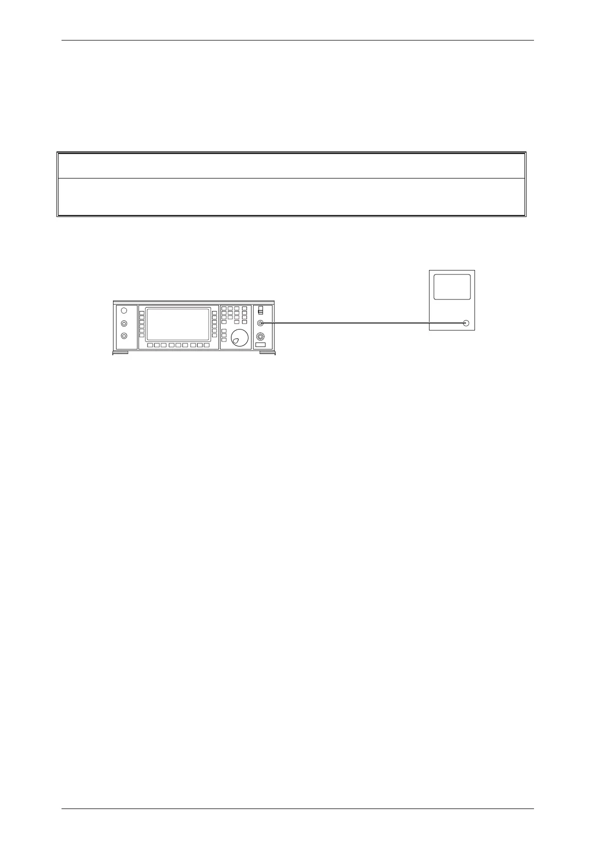
(1) Connect the test equipment as shown in Fig. B-31.
C0564
UUT
LF OUTPUT
Oscilloscope
➤
Fig. B-31 Waveform phase control test set-up
(2) Set up the test equipment as follows:
Unit under test
[UTIL] [Mod'n Mode] [Composite]
[SIG GEN]
LF output Modulation monitor
Modulation drive
AM1 30% ON
AM2 30 % ON
INT F1 30 Hz
INT F2 30 Hz
Set AM1 source to INT F1
Set AM2 source to INT F2
Oscilloscope
Set to monitor LF OUTPUT waveform .
(3) On the UUT select the Internal Source Selection menu and press the
[Mod. Src Phase] key. Enter a phase of 0° (to beacon).
Check that the LF OUTPUT is approximately 1.69 V pk-pk.
(4) Enter a phase of 180°. Check that the output tone is substantially suppressed to a
level less than 80 mV pk-pk.
(5) Enter a phase of 90° and check that the output tone is approximately 1.2 V pk-pk.
(6) Enter a phase of 270° and check that the output tone has the same amplitude as in
(5) above.

 Loading...