ACCEPTANCE TESTING
5-1-6
Attenuator accuracy
The following test will confirm that the attenuator performs to the published performance
specification. In the event of the receiver/down converter not being available, an alternative
method to functionally test the attenuator is also suggested (see 'Alternative attenuator functional
check' below).
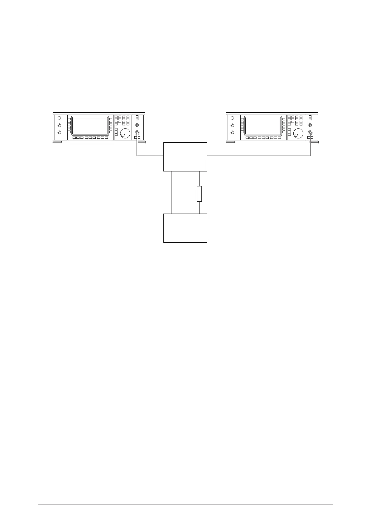
Fig. 5-1-2 Attenuator accuracy test set-up
(1) Connect the test equipment as shown in Fig. 5-1-2.
(2) Set the UUT to [RF Level] 0 dBm [Carrier Freq.] 2.5 MHz.
(3) Tune the receiver to 2.5 MHz and measure the RF level.
(4) Set the UUT to [RF Level] -6.1 dBm and measure the RF level.
(5) Decrement the output of the UUT in 6 dB steps down to an RF level of
-120.1 dBm measuring the RF level at each step. Check that the measured level is
within specification.
(6) Repeat (2) to (5) at the frequencies given in Table 5-1-3.
(7) Set the local oscillator to +8 dBm at the frequencies indicated in brackets in
Table 5-1-3.
C0121
RF OUTPUTRF OUTPUT
Sensor
UUT Signal Generator
Measuring
Receiver
Frequency offset
mode connection
➤
➤
➤
➤
Down
Converter
RF LO
IF

 Loading...