OPTION 005 GMSK Bt 0.3
Annex A-11
Configuration select
Configuration select is used to set the way in which the GSM generator interacts with
internal and external control signals. To set up the GSM configuration, press the
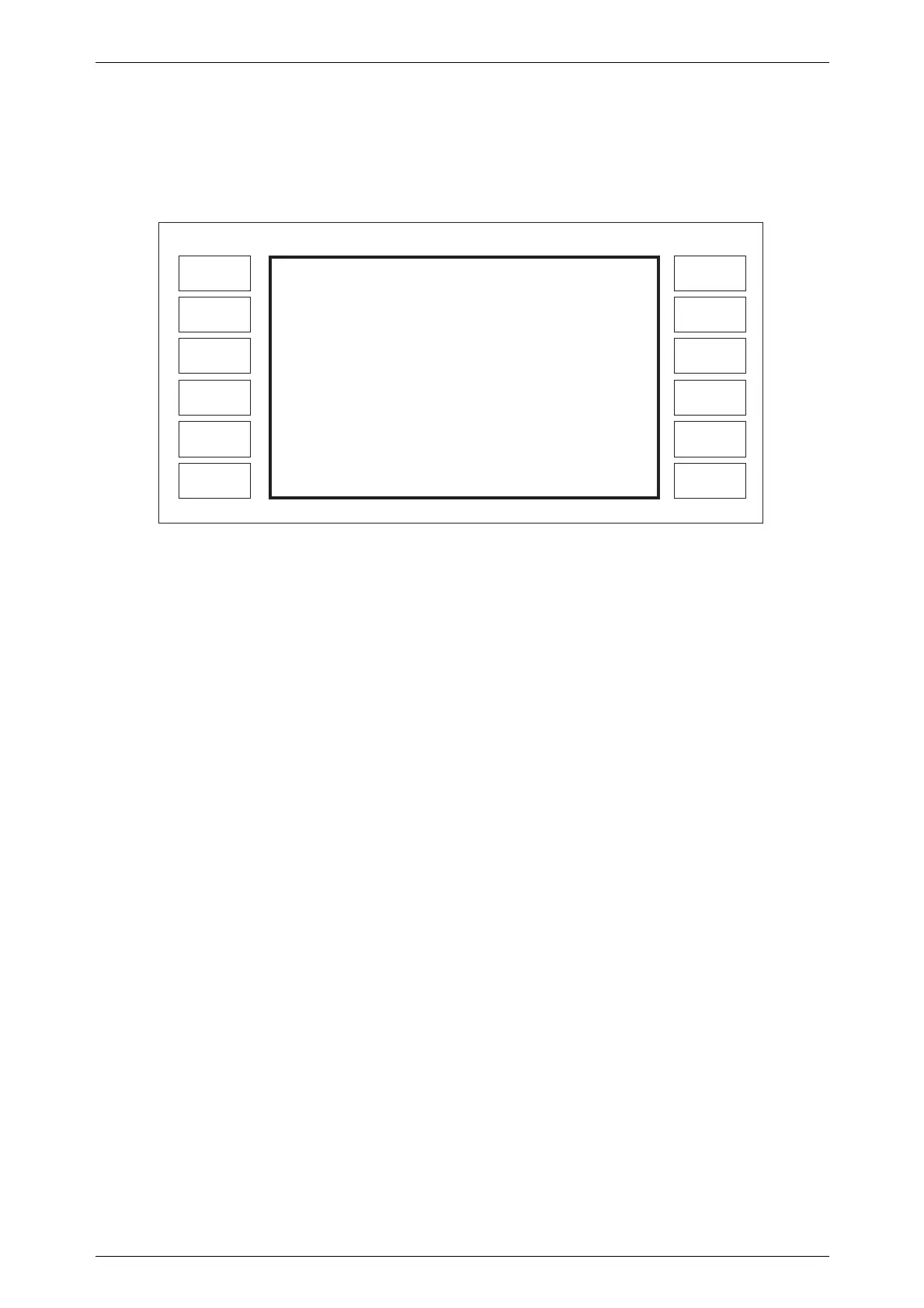
[ConFig. Select] key shown in Fig. A-5 to obtain the menu shown in Fig. A-7.
Mod
Polarity
Master
Slave/SA
Doppler
Trigger
Select
Sideband
U/L/Auto
LOCAL
GMSK
Fidelity
Diff.
Encoding
Envelope
Select
EXIT
GMSK Configuation Select
C0343
Trigger Control
Config Control
Doppler
Sideband
Mod. Polarity
GMSK Fidelity
Diff. Encoding
Envelope Control
CONTINUOUS
STAND ALONE
DISABLED
UPPER
NORMAL
NORMAL
ENABLED
DISCONTINUOUS
:
:
:
:
:
:
:
:
*
*
[
*
Internal data control only
]
Fig. A-7 GMSK configuration selection menu
Trigger control
The [Trigger Select] key can be set to continuous or single trigger operation. In
continuous mode the data from the internal data generator is repeated continuously while in the
single mode the data is only generated once.
Configuration control
When using the internal data generator the instrument may be set to stand alone, master
or slave mode using the [Master/Slave/SA] key. When STAND ALONE is selected the
instrument responds in the normal way to GPIB or keyboard commands. When MASTER is
selected the instrument generates a clock output from the CLOCK connector and a synchronizing
signal from the SYNC connector on the rear panel. By connecting the clock and sync signals to a
generator set to the slave mode the master will control the timing of the data generator in the
slave instrument such that if the two RF signals are compared their slot structures are in
synchronism. This allows the generator to be used in applications requiring two or more sources
of GMSK signal.
Doppler
With Doppler set to ENABLED the DOPPLER input on the rear panel of the instrument
may be used to frequency modulate the carrier using an external source to simulate the effect of
Doppler frequency shifts. The DOPPLER input can also be used to add FM signals to simulate
the effect of receiving signals with a GMSK phase error .
The sensitivity, in Hz/V, of the DOPPLER input is displayed on the Sig. Gen. Menu
(Fig. A-6). The sensitivity is carrier frequency dependent since it uses the same input as
Wideband FM and the instrument sets the sensitivity to be close to 500 Hz/V or the minimum
sensitivity available (at 2 GHz the minimum sensitivity is typically 1200 Hz/V).

 Loading...