OPTION 010 DME Modulator
Annex-E-13
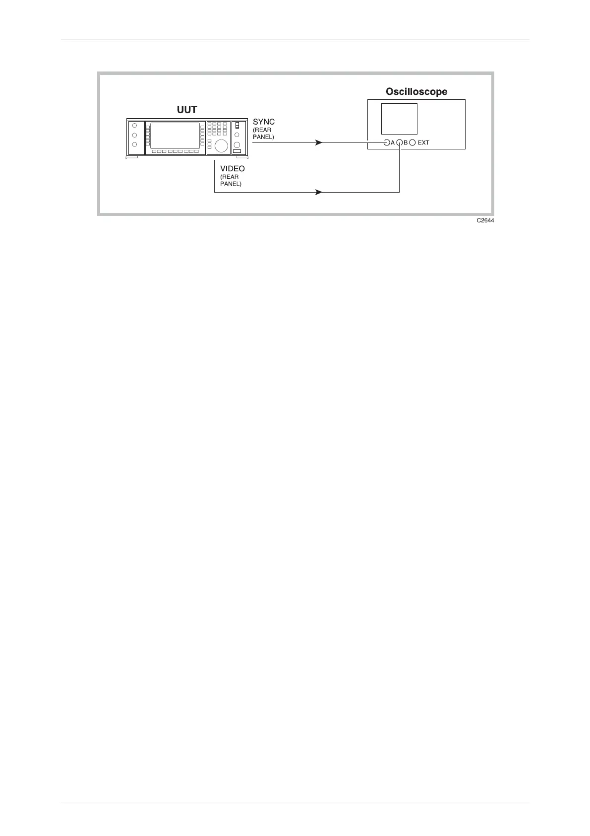
Fig. E-11 Pulse generator functional test set-up; continuous mode
(1) Connect the test equipment as shown in Fig. E-11.
(2) Set up the equipment as follows:
Unit under test:
Modulation mode Avionics, DME
Oscilloscope:
A & B volts/div 1 V DC
Timebase 1 µs/div
Trigger A
Pulse generator:
Continuous square wave
Period 100 µs
Level OFF / ON 0 V / 5 V into 50 Ω
(3) The oscilloscope will display the traces shown in Fig. E-12a. The SYNC pulse
width should be 400 ns. The VIDEO pulse should be gaussian shaped, with pulse
width of 3.50 µs and rise and fall times of 2.50 µs. Amplitudes should be +2.5 V
for both SYNC and VIDEO, providing the oscilloscope has 50 Ω inputs, or 50 Ω
feed-throughs are used. High impedance inputs will produce nominal amplitudes
of +5 V.
Reducing the timebase to minimum will show the rise time of the sync pulse. This
is typically <2 ns.
Increasing the timebase to 20 µs/div will produce the display shown in Fig. E-12b.
Default values are 6000 pps (166 µs) for the repetition rate and 12 µs for the pulse
pair spacing.

 Loading...