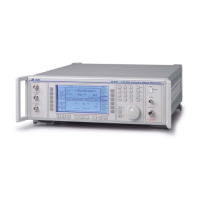
OPERATION
3-1-5
(1) SUPPLY Switches the AC supply voltage on and off.
(2) CARR ON-OFF
Enables or disables the carrier frequency.
(3) MOD ON-OFF
Enables or disables the modulation.
(4) LF ON-OFF
Switches the low frequency output on and off.
(5) UTIL
Displays the utilities menu.
(6) MEM
Displays the memory store/recall menu.
(7) Δ
Displays the total shift menu.
(8) LF
Displays the LF and monitor menus.
(9) SWEEP
Displays the sweep status menu.
(10) SIG GEN
Displays the main menu.
(11) SOFT KEYS;
Twelve function keys change notation as the menu changes.
(12) NUMERICAL
KEY PAD
For changing the value of a selected parameter. Minus sign and
decimal point are included.
(13) UNITS KEYS
Determine the units of set parameters and terminate the numerical
entry.
(14) CONTROL KNOB
When enabled, adjusts the value of the selected parameter.
(15) ⇑ ×10
When knob disabled, increments a selected parameter. When
knob enabled, increases knob sensitivity by factor of ten.
(16) KNOB UP-DN
Switches between control knob and ⇑⇓ keys.
(17) ⇓ ÷10
When knob disabled, decrements a selected parameter. When
knob enabled, decreases knob sensitivity by factor of ten.
(18) LF OUTPUT
BNC socket provides a low impedance output at the frequency
selected at the LF GENERATOR MENU or monitors the
modulating signal.
(19) RF OUTPUT
50 Ω N type socket with reverse power protection.
(20) PULSE
INPUT
50 Ω BNC socket (if fitted) accepts a pulsed signal.
(21) EXT MOD 1
INPUT
100 kΩ BNC socket. An independent input which allows an
external modulation signal to be applied.
(22) EXT MOD 2
INPUT
100 kΩ BNC socket, similar to (21).

 Loading...