7713395 R2 139
8.8. Honeywell Burner Control Fault Codes
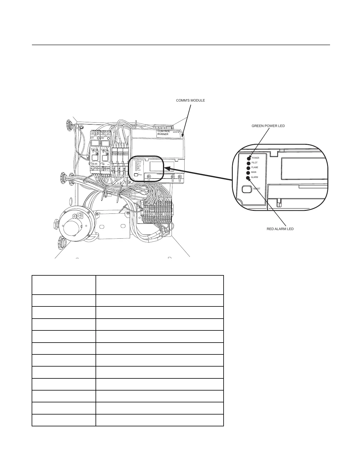
The Honeywell burner control system displays system faults by illuminating the red ALARM LED, and turning the
green POWER LED on and off in patterns. The patterns consist of one or more fast, and one or more slow,
flashes of the POWER LED. These patterns are sometimes referred to as “blink codes”. The following table
provides a description of the “blink codes” and their meanings.
Figure 156. Honeywell burner control location and LEDs
BURNER
CONTROL
POWE
R
PILO
T
FLAM
E
ALAR
M
RU
N
LIMI
T
RESE
T
MAI
N
120
V
120
V
120
V
MV1
GND
GND
BK7
BUS
MV2
PV
L
V
N
N
N
N
MODE
3
1 2
TB
TB
45
E
4
5 6
7 8
1 2
3
1 2
M
KS
45
rail
rail
1
1
12 13
OUT
OUT
3
OUT
4
PW
R
OUT
LC
14
15 16 17 18
1
1
12 13 14
15 16 17 18
E
4
PW
R
GREEN POWER LED
RED ALARM LED
RESET
ALARM
MAIN
FLAME
PILOT
POWER
COMM'S MODULE
Table 13. Power LED fault codes
CODE
(Fast-Slow)
FAULT DESCRIPTION
1-1
Low AC line voltage
1-2
AC quality problem
2-1
Unexpected flame signal
2-2
Flame signal absent
2-3
Flame signal overrange
3-1
Running ILK switch problem
3-2
Running ILK switch in Standby
3-3
Valve proving fault
4-1
Purge card problem
4-2
Wiring problem/internal fault
4-3
Flame amplifier problem
CONTINUOUS MIXED-FLOW GRAIN DRYER WITH COMMANDER CONTROL SYSTEM 8. APPENDIX