7713395 R2 31
3.4. Burner Control and Temperature Control
Electrocution Hazard
• Know where the main shut-off is.
• Make sure all required personnel are trained.
• Observe all safety rules when working with the electrical system
• Use lockout/tagout.
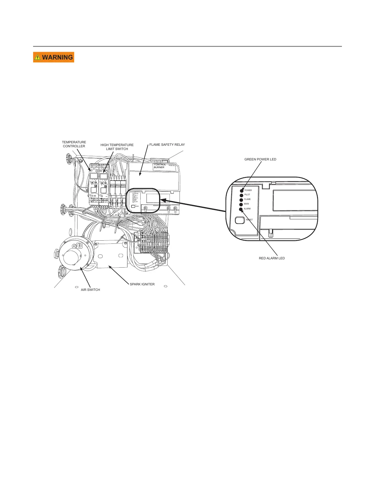
Burner Control Box Components
Figure 24. Burner box components
BURNER
CONTROL
POWE
R
PILO
T
FLAM
E
ALAR
M
RU
N
LIMI
T
RESE
T
MAI
N
120
V
120
V
120
V
MV1
GND
GND
BK7
BUS
MV2
PV
L
V
N
N
N
N
MODE
3
1 2
TB
TB
45
E
4
5 6
7 8
1 2
3
1 2
M
KS
45
rail
rail
1
1
12 13
OUT
OUT
3
OUT
4
PW
R
OUT
LC
14
15 16 17 18
1
1
12 13 14
15 16 17 18
E
4
PW
R
GREEN POWER LED
RED ALARM LED
RESET
ALARM
MAIN
FLAME
PILOT
POWER
FLAME SAFETY RELAY
HIGH TEMPERATURE
LIMIT SWITCH
TEMPERATURE
CONTROLLER
AIR SWITCH
SPARK IGNITER
The Burner Box contains five primary components, which work together to control the combustion inside the
dryer. They are:
• The Air Switch checks for airflow across the burner.
• The Spark Igniter sends voltage to the spark plug to light the pilot.
• The KS45 Temperature Controller sends and receives temperature data.
• The TB45 High Temperature Limit Switch allows manual control of the high temperature setting by
adjustment of the knob. If the high temperature limit is exceeded, the dryer shuts down immediately with
NO cool-down period.
• The Honeywell Flame Safety Relay checks functions related to combustion:
– Absence of pilot flame
– Adequate air flow
– Presence of burner flame
– High Temperature Limit
– Controls outputs for ignition, inlet valves, pilot valve, main valve, and burner reset.
CONTINUOUS MIXED-FLOW GRAIN DRYER WITH COMMANDER CONTROL SYSTEM 3. FEATURES