30 7713395 R2
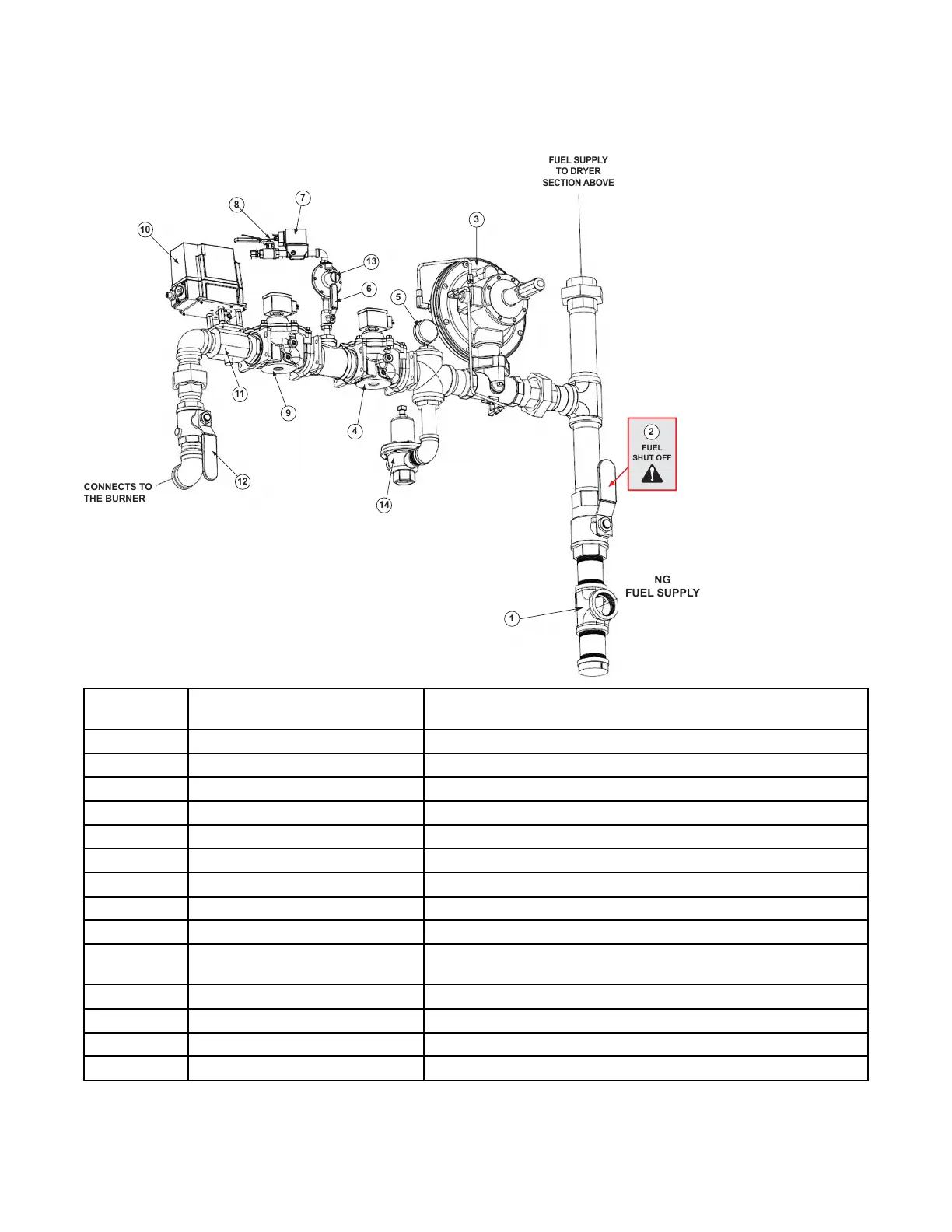
3.3.2 Natural Gas (NG)
Figure 23. NG fuel layout
FUEL SUPPLY
TO DRYER
SECTION ABOVE
Item # in
Diagram
Component Description
1
Fuel supply inlet The main fuel supply connects at this location.
2 Fuel shut–off valve
The fuel supply for ALL dryer sections can be shut off here.
3
Pressure regulator Reduces fuel pressure to the downstream sections of the fuel system.
4 Main valve 1
Electrically actuated valve to turn fuel ON or OFF to the pilot and burner.
5
Pressure gauge Indicates fuel pressure at the regulator output.
6 Pilot shut-off valve
Manual valve for shutting off fuel to the pilot.
7 Pilot solenoid valve
Electrically actuated valve to turn the fuel ON or OFF to the pilot.
8 Pilot line
Supplies fuel to the pilot.
9 Main valve 2
Electrically actuated valve to turn the fuel ON or OFF to the burner.
10
Electronic modulating motor
Receives signal from the temperature controller. Moves a linkage attached
to the butterfly valve to modulate the fuel flow to the burner.
11
Butterfly valve Controls flow of fuel to the burner to maintain the desired temperature.
12 Burner shut-off valve
Manually operated to shut off fuel to the burner
13
Pilot Pressure Regulator (CSA Only) Further reduces fuel pressure to the pilot solenoid valve
14
Overpressure relief valve Vents excessive pressure that may build up downstream of the regulator
3. FEATURES CONTINUOUS MIXED-FLOW GRAIN DRYER WITH COMMANDER CONTROL SYSTEM