34 7713395 R2
Fire Hazard
Observe the temperature values regularly to ensure that the system is working properly. At the
beginning of each drying season, test the high limit shut-off system.
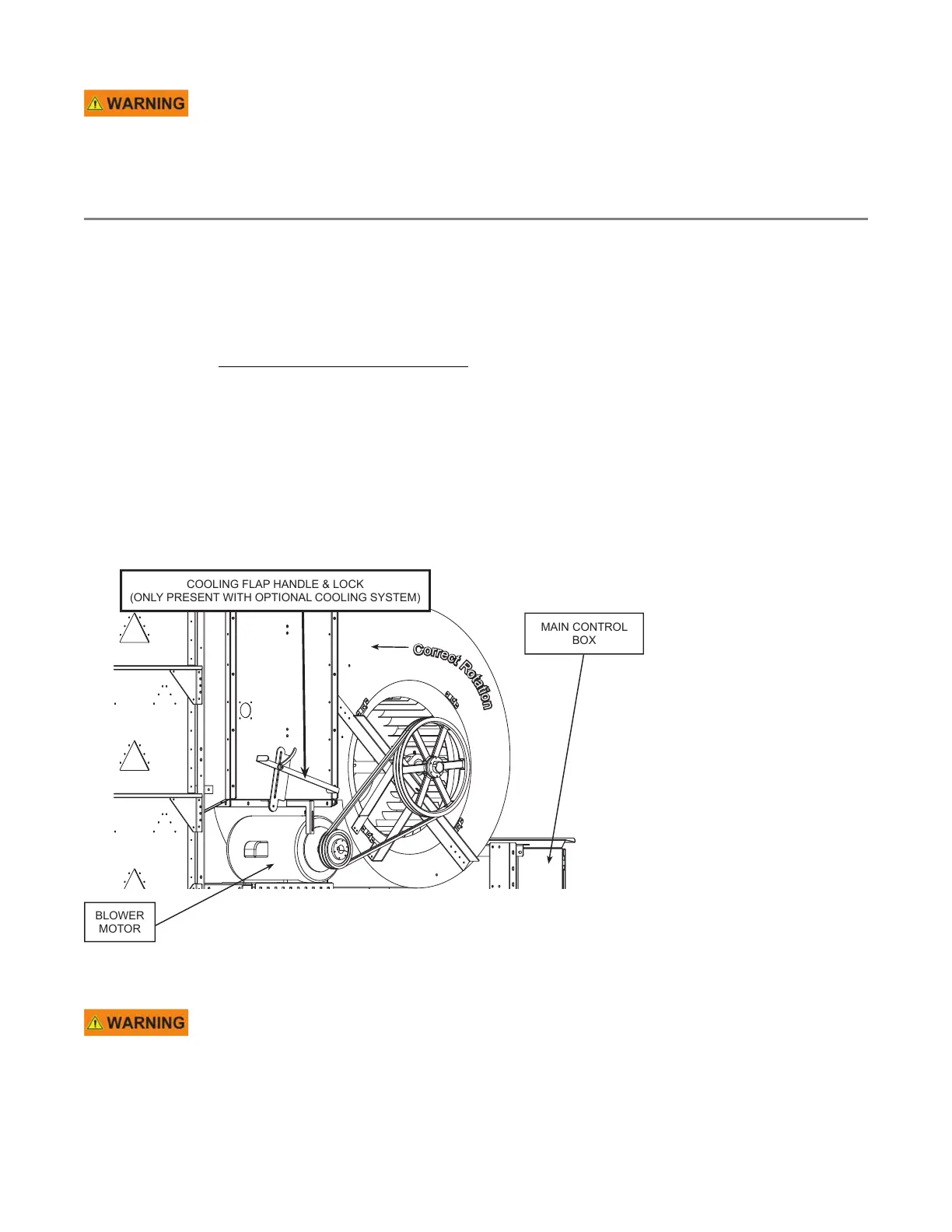
3.5. Blower System
• The blower motor, pulley, and blower housing are located at the lowest level of each dryer section. A
transition housing connects the blower housing to specific tiers of that section.
• Proper airflow is verified by the static pressure air switch located within the burner box.
• The primary purpose for the blower system is to provide airflow for each dryer section. Most blower/
transition housings include a burner system. However, a bottom dryer section can be ordered with a blower,
but NO burner. This would be used for cooling only.
• The blower motor size is provided per dryer configuration and customer requirements, and ranges from 15
to 30 HP.
• Refer to Section 7.1 – Standard Model Specifications on page 125 for more information, including total air
flow, etc.
• The blower system in the lowest dryer section with a burner can also include an optional system that will
cool grain using cooling floors and cooling doors. See Section 3.6 – Grain Cooling System (optional) on page
35.
Figure 28. Blower system
C
o
r
r
e
c
t
R
o
t
a
t
i
o
n
BLOWER
MOTOR
COOLING FLAP HANDLE & LOCK
(ONLY PRESENT WITH OPTIONAL COOLING SYSTEM)
MAIN CONTROL
BOX
Note
Shown without safety guard for clarity.
Do not run the dryer without the proper guard in place.
3. FEATURES CONTINUOUS MIXED-FLOW GRAIN DRYER WITH COMMANDER CONTROL SYSTEM