146 7713395 R2
8.10. HMI Wiring Connections
Important
The HMI must be connected to a customer-supplied 120 VAC, 400 to 600 VA uninterruptible power
supply (UPS).
Electrical Wiring from Main Control to HMI
1. Using the labels provided, pull and connect the following wires from the main control terminals to the HMI
terminals:
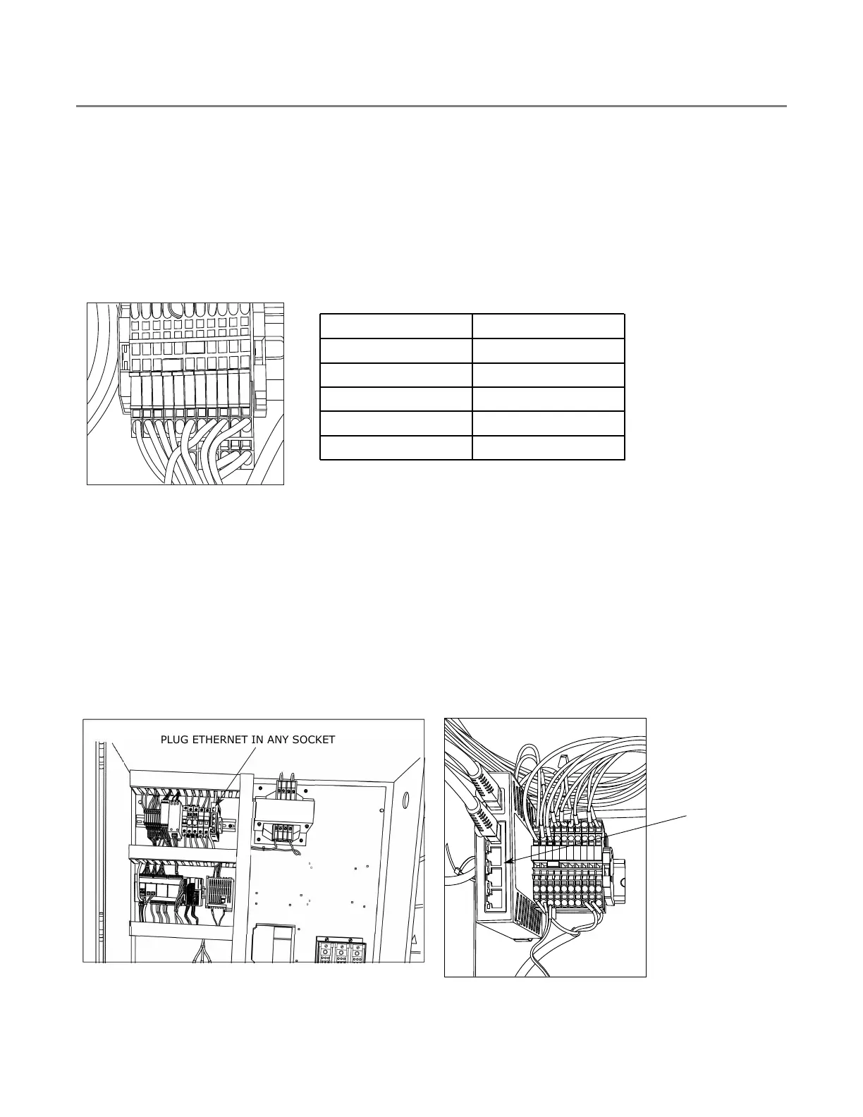
Figure 157. Terminals Inside HMI Enclosure
E1A
E2
E2A
0V
Z
H
0V
24V
24V
120V
GND
Wire Label
Wire Color
E1A Blue
E2 Blue
E2A Blue
24V Blue
0V White
Ethernet Cable from Main Control to HMI
1. Pull Cat 6 shielded Ethernet cable from the main control to the HMI. The maximum distance should be less
than 300 feet.
2. Terminate each end of the Ethernet cable (if not already terminated).
3. Plug one end into the ethernet switch in the main control panel.
4. Plug the other end into the Ethernet switch inside the HMI enclosure.
Figure 158. Ethernet Cable Connection in Main
Control Panel
0
0
0
0
PLUG ETHERNET IN ANY SOCKET
Figure 159. Ethernet Cable Connection in HMI
Cabinet
5ES
5
4
3
2
1
100
LNK
120V
EIA
E2A
24V
GND
E2
OV
OV
H
N
5-Port Industrie
PLUG ETHERNET
IN ANY SOCKET
8. APPENDIX CONTINUOUS MIXED-FLOW GRAIN DRYER WITH COMMANDER CONTROL SYSTEM