32 7713395 R2
Burner Box Cable(s)
• The grey cable entering the left side of the burner box(es) from each modulating motor is pre-wired at
NECO. This cable signals the modulating motor to adjust the butterfly valve, controlling the flow of fuel.
• The yellow burner cable(s) and the grey communication cable(s) are used between each burner box and also
from the lowest burner box to the main control box.
– The yellow cable connects to the T-connector on the top burner box, as does the yellow splitter cable for
the fill and low switches.
– The grey cable plugs directly into the top burner box, while the T-connector is used for lower burner
boxes when present.
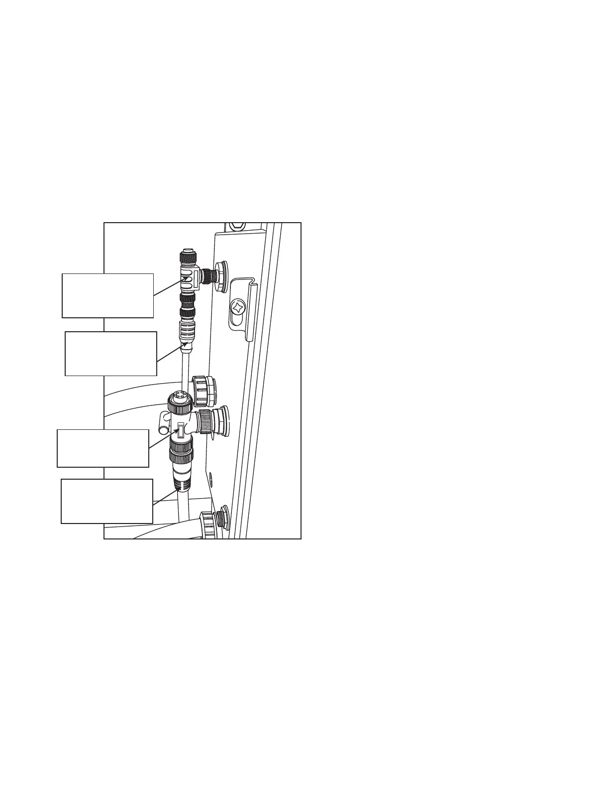
Figure 25. Burner box cable connections
GREY
CABLE
YELLOW
BURNER CABLE
TEE
GREY
COMMUNICATIONS
CABLE TEE
COMMUNICATIONS
YELLOW
BURNER
CABLE
Components Located at Each Burner
• The spark plug lights the pilot upon signal from the spark igniter.
• The UV sensor checks for two separate conditions relating to the absence or presence of flame.
• The pilot fuel line supplies the fuel for the pilot. This line comes from the main fuel train and has its own
manual shut-off, pressure regulator, and solenoid valve.
• The air switch line is connected to the air switch and must sense airflow in order for the burner to light and
stay lit.
3. FEATURES CONTINUOUS MIXED-FLOW GRAIN DRYER WITH COMMANDER CONTROL SYSTEM