26 7713395 R2
LP Fuel - Inlet Section
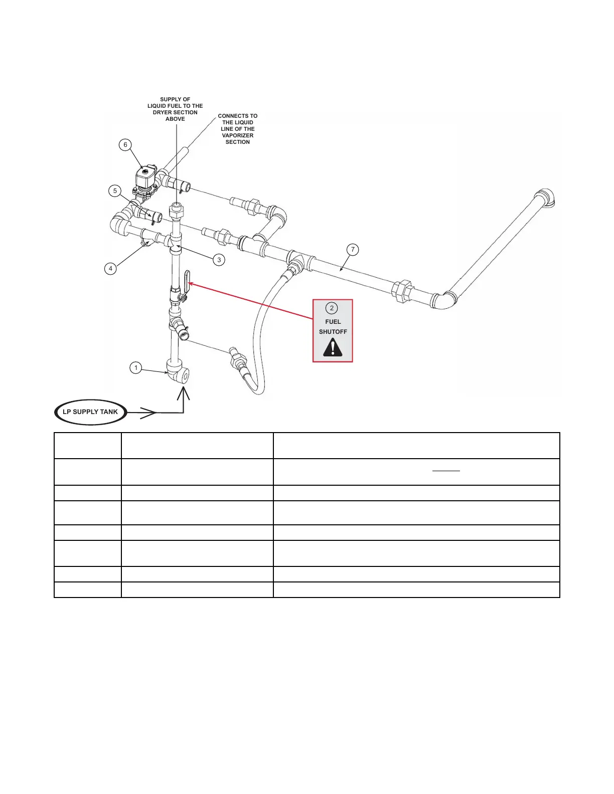
Figure 19. LP fuel — inlet section
CONNECTS TO
THE LIQUID
LINE OF THE
VAPORIZER
SECTION
SUPPLY OF
LIQUID FUEL TO THE
DRYER SECTION
ABOVE
Item # in
Diagram
Component Description
1
Fuel supply inlet elbow
The main fuel supply connects here on the bottom dryer section. Note that
the top dryer section also uses an elbow.
2 Fuel shut–off valve
The fuel supply for ALL dryer sections can be shut off here.
3
Fuel supply “T” and transfer line
All middle dryer sections connect here. The upper-most dryer section has an
elbow at this location.
4 Fuel strainer
The fuel strainer traps foreign debris that may be in the liquid fuel line.
5
Hydrostatic relief valve
The hydrostatic relief valve relieves the hydrostatic pressure that may
develop in sections of liquid piping between closed shutoff valves.
6
Liquid solenoid valve This is an electrically actuated valve to turn fuel ON or OFF.
7
Vent pipe assembly (CSA Only) This piping carries away any liquid discharged from hydrostatic relief valves.
3. FEATURES CONTINUOUS MIXED-FLOW GRAIN DRYER WITH COMMANDER CONTROL SYSTEM