© Agilent Technologies 2001–2003 Agilent 3070 System Installation Manual (MS Windows Version) 1-34
Chapter 1: MS Windows System Installation Procedure: Enabling the Testhead
Description of ControlXT/XTP LED Sequencing
1 After about 2 minutes LED activity will begin.
2 Some various quick green-LED activity will be seen,
then LED7 will flash for about 30 seconds.
3 More quick LED activity will occur including some
red LEDs on for only about 2 seconds.
4 The sequence concludes successfully with green
LEDs 5 and 7 continuously toggling opposite each
other (heartbeat condition).
No red LEDs should remain on. If the testhead
encounters boot errors, verify the bootptab file
contains the unique hardware address of the control
card. See the Agilent 3070 / 79000 Repair Manual.
Check the System Config File
NOTE
Non-matching config files can result from the
controller being shipped separate from the
testhead, or if testhead cards have been moved.
NOTE
The Actual Config function key F4 polls the cards
in the testhead to identify their type.
1 Compare the system and standard config files to the
configuration printouts shipped with the system:
Open a Korn shell window: Click Start > Programs >
Agilent 3070 > Korn Shell.
2 At the prompt enter:
cd $AGILENT3070_ROOT/diagnostics/th1
then,
more config
NOTE
For more information about
$AGILENT3070_ROOT, see “The Root Directory
Environment Variable” in Chapter 2.
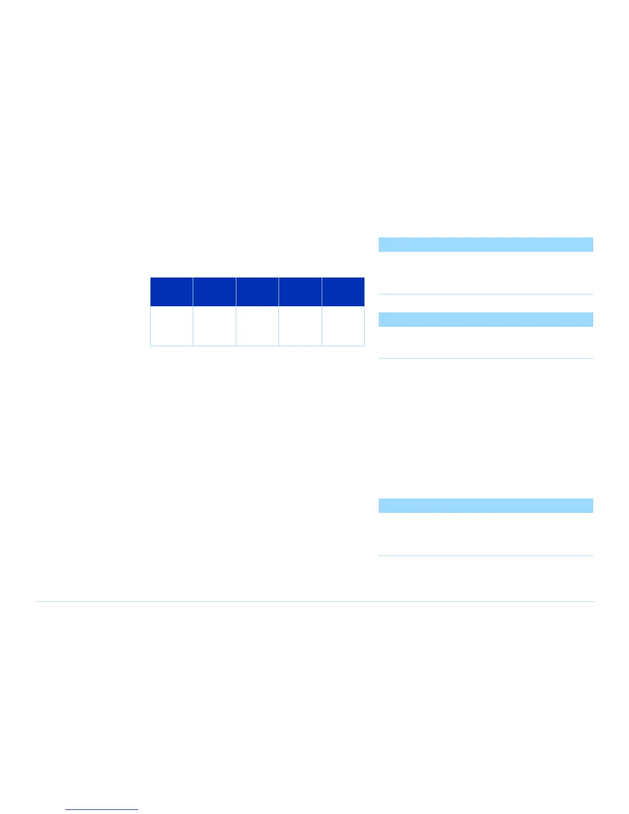
Table 1-4 ControlXT/XTP Card status LEDs (as viewed
from the card edge)
LED
Ref Des 6 7 4 5 2 3 0 1
Color
R=Red
G=Green
■ ■
RG
■ ■
RG
■ ■
RG
■ ■
RG