2- 11
Making Mixer Measurements
Measurement Considerations
The following steps can be performed to observe this offset in power:
1. To set the power range to manual, press:
Setting the power range to manual prevents the internal source attenuator from switching when
changing power levels. If you choose a different power range, the R channel offset compensation and R
channel measurement changes by the amount of the attenuator setting.
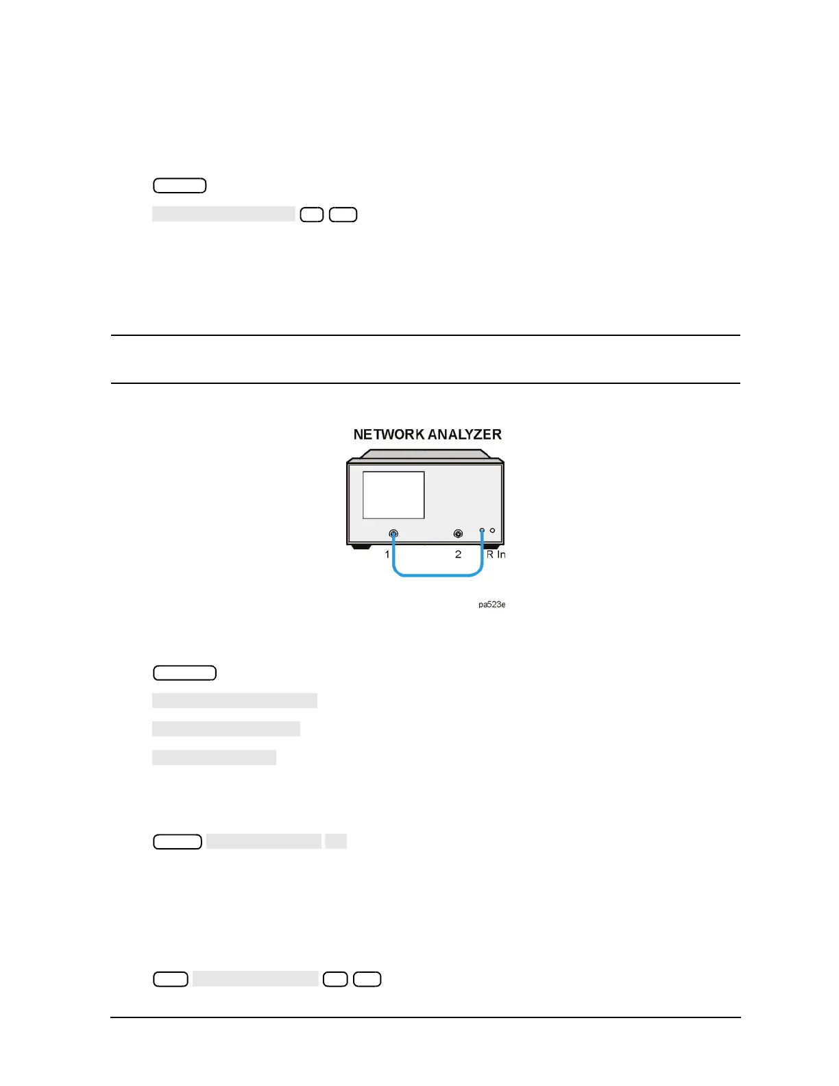
2. Connect the analyzer source output, port 1, directly to the R channel input as shown in Figure 2-9.
CAUTION To prevent connector damage, use an adapter (part number 1250-1462) as a connector saver
for R CHANNEL IN.
Figure 2-9 R Channel External Connection
3. To activate the frequency offset mode, press:
Since the LO (offset) frequency is still set to the default value of 0 Hz, the analyzer will operate normally.
4. Measure the output power in the R channel by pressing:
Observe the 13 to 16 dB offset in measured power. The actual input power level to the R channel input
must be 0 dBm or less, 10 dBm typical, to avoid receiver saturation effects. The minimum signal level
must be greater than 35 dBm to provide sufficient signal for operation of the phaselock loop.
5. You cannot trust R channel power settings without knowing about the offset involved. Perform a receiver
calibration to remove any power offsets by pressing:
 Loading...


