6-20
Calibrating for Increased Measurement Accuracy
Frequency Response and Isolation Error Corrections
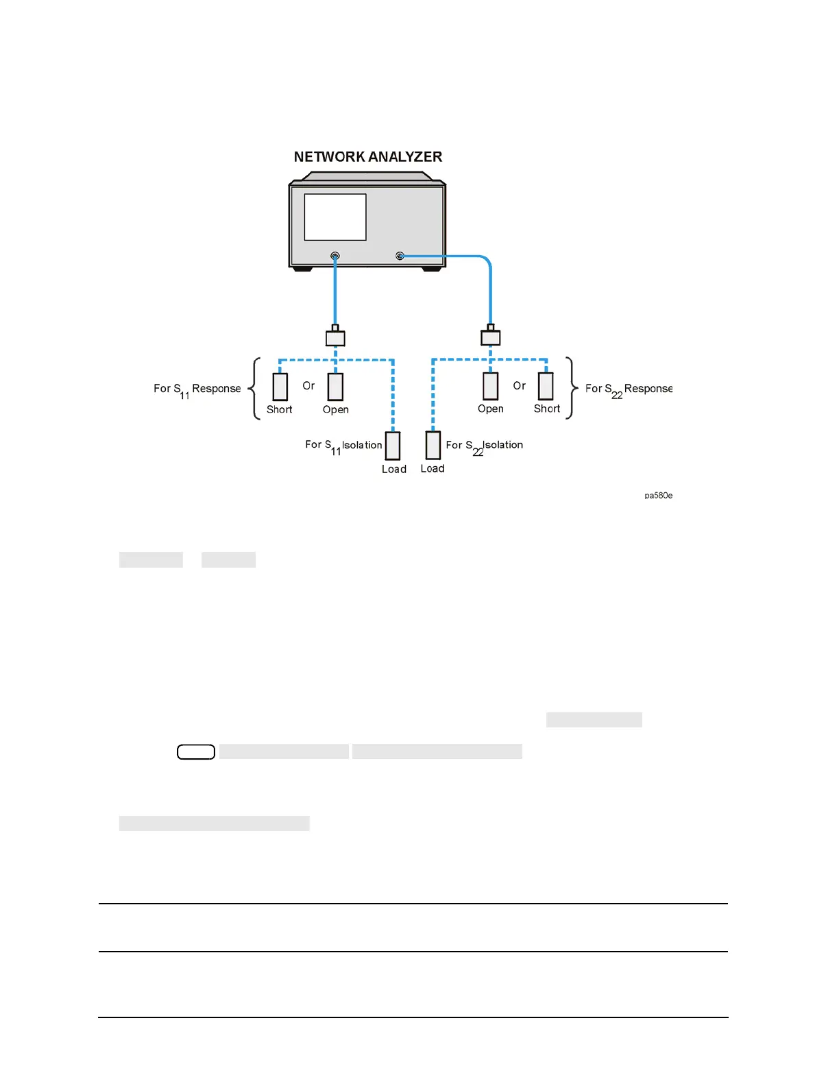
Figure 6-6 Standard Connections for a Response and Isolation Error Correction for Reflection
Measurements
8. To measure the standard, press:
or
If the calibration kit you selected has a choice between male and female calibration standards,
remember to select the sex that applies to the test port and not the standard.
The analyzer displays WAIT - MEASURING CAL STANDARD during the standard measurement. The
analyzer underlines the softkey that you selected after it finishes the measurement, and computes the
error coefficients.
9. Connect the load calibration standard to the test port.
10. To measure the standard for the isolation portion of the correction, press .
a. Press and enter at least four times more
averages than desired during the device measurement.
11. To compute the response and directivity error coefficients, press:
The analyzer displays the corrected S
11
(or S
22
) data. The analyzer also shows the notation Cor to the
left of the screen, indicating that the correction is switched on for this channel.
NOTE You can save or store the error correction to use for later measurements. Refer to Chapter 4 ,
“Printing, Plotting, and Saving Measurement Results” for procedures.
12. This completes the response and isolation error correction for reflection measurements. You can

 Loading...


