164 Chapter 6
Replacement Procedure
Replacing an Assembly
Replacing an Assembly
The following steps show the sequence for replacing an assembly in a E5071C RF
Network Analyzer.
1. Identify the faulty group. Refer to Chapter 4, “Troubleshooting.”
2. Order a replacement assembly. Refer to Chapter 5, “Replaceable Parts.”
3. Replace the faulty assembly and determine what adjustments are necessary. Refer to
this chapter and
Chapter 7, “Post-Repair Procedures.”
4. Perform the necessary adjustments. Refer to Chapter 3, “Adjustment.”
5. Perform the necessary performance tests. Refer to Chapter 2, “Performance Test.”
WARNING These servicing instructions are for use by qualified personnel only. To avoid
electrical shock, do not perform any servicing unless you are qualified to do so.
WARNING The opening of covers or removal of parts is likely to expose dangerous voltages.
Disconnect the instrument from its power supply.
CAUTION Many of the assemblies in this instrument are very susceptible to damage from ESD
(electrostatic discharge). Perform the following procedures only at a static-safe workstation
and wear a grounding strap.
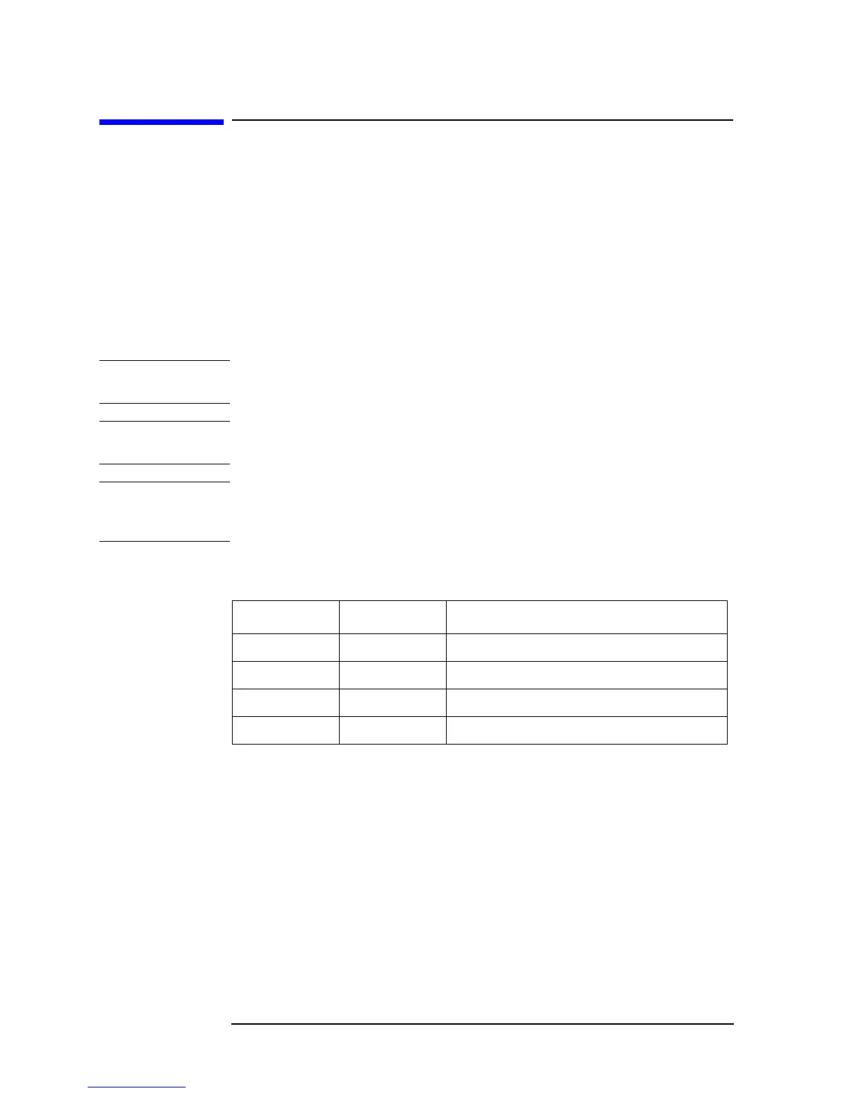
Please refer to the following table for the tightening torque of screws if no torque is
specified by this chapter.
Screw Driver Recommended Torque
M2.5 T8 0.56 N-m ( 5.0 lb-in)
M3 T10 1.02 N-m ( 9.0 lb-in)
M3.5 T15 1.58 N-m (14.0 lb-in)
M4 T20 2.37N-m (21.0 lb-in)
 Loading...