226 Chapter 6
Replacement Procedure
PCA DC Bias Board (Opt.xx5) Replacement (A57/A58)
PCA DC Bias Board (Opt.xx5) Replacement (A57/A58)
Tools Required
• TORX screwdriver, T10, T15, and T20
• Open-end torque wrench, 9/16 inch (set to 3.46 N-m / 30.5 lb-in)
Removal Procedure
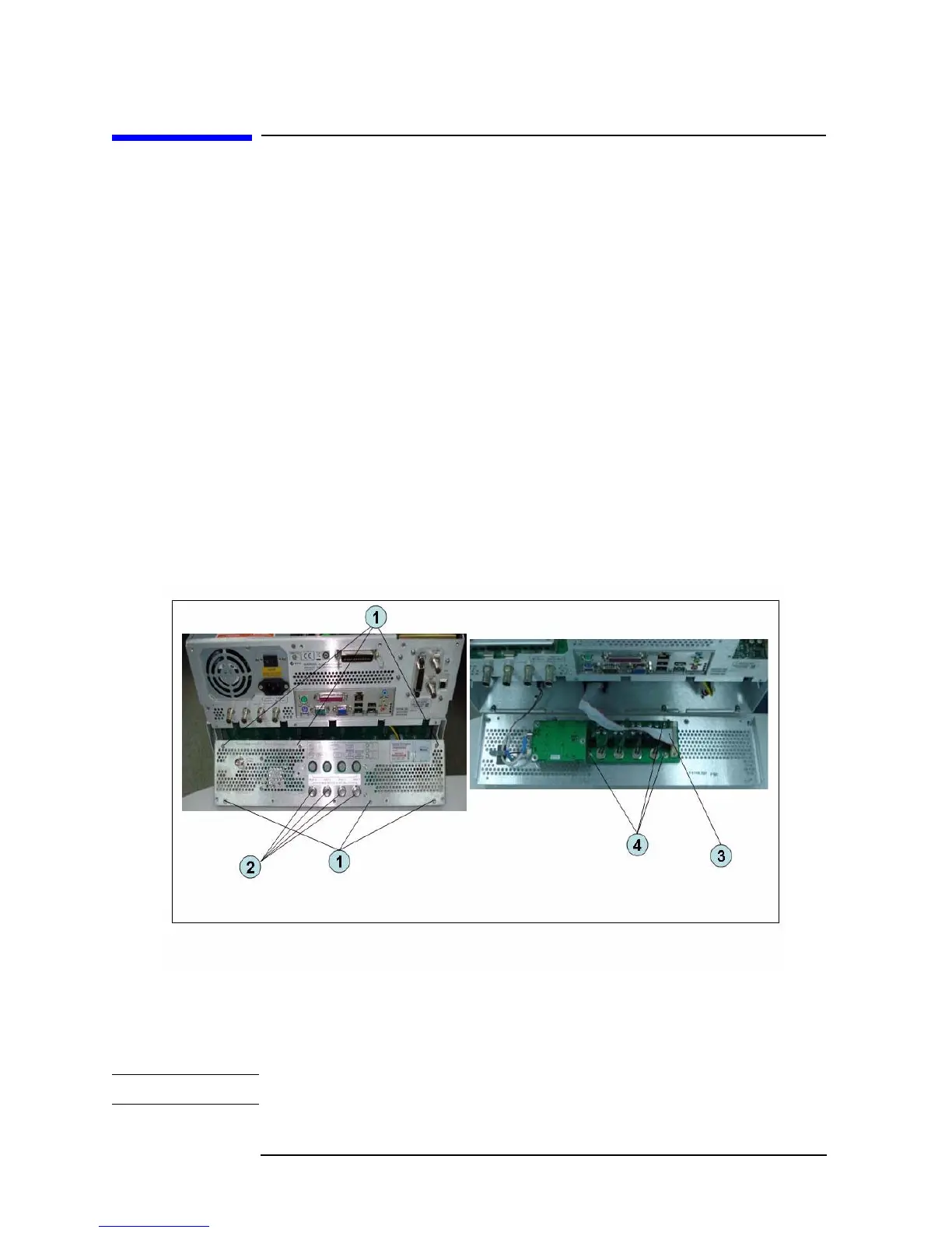
Refer to Figure 6-30 for this procedure.
Step 1. Remove the outer cover as described in “Outer Cover Removal” on page 167.
Step 2. Remove the 9/16 inch nut (item 2) fastening the rear cover.
Step 3. Remove the six TORX T10 screws (item 1) fastening the rear cover.
Step 4. Disconnect the cable (item 3) from the analog motherboard.
Step 5. Remove the three TORX T10 screw (item 4) fastening the DC Bias board.
Figure 6-31 PCA DC Bias Board Removal
Replacement Procedure
Step 1. Replace the PCA DC bias board by inverse procedure of removal.
NOTE Fasten the 9/16 inch nuts (item 2) using a open-end torque wrench.
 Loading...