Getting Started 2
N9310A User’s Guide 27
Connectors Maintenance
Check the connectors at least every six months—more often
if the instrument is used daily on a production line or in a
harsh environment.
Visually inspect the front panel connectors. The most impor-
tant connectors are those to which the DUT (device under
test) is connected, typically the RF cable end or the RF OUT
and LF OUT connectors. All connectors should be clean and
the center pins centered. The fingers of female connectors
should be unbroken and uniform in appearance. If you are
unsure whether the connectors are good, gauge the RF OUT
connectors to confirm that their dimensions are correct.
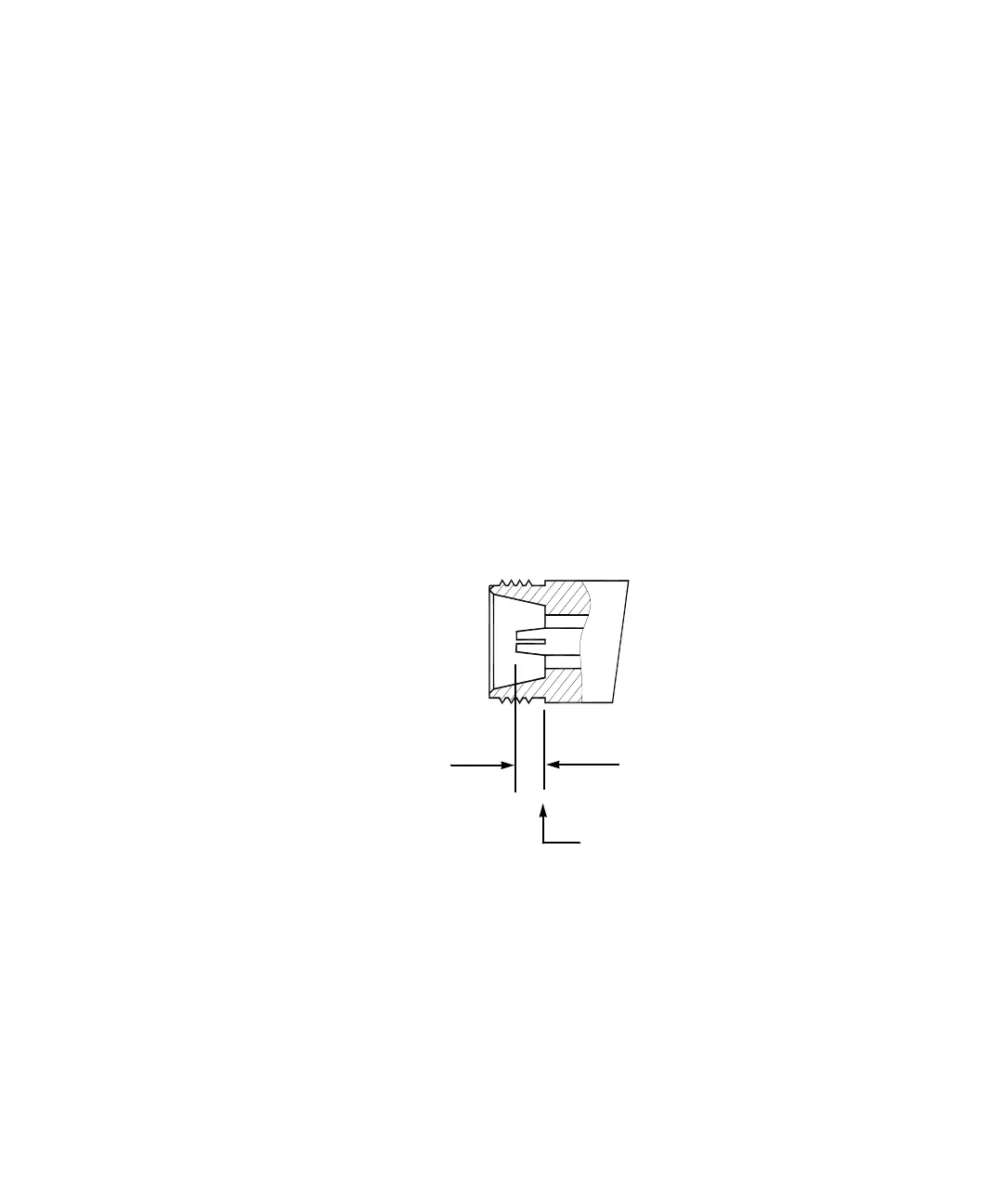
Maximum and minimum protrusion of center conductor from mating plane
Min. = 0.204 in. Max = 0.207 in.
Mating plane