Overview 1
N9310A User’s Guide 9
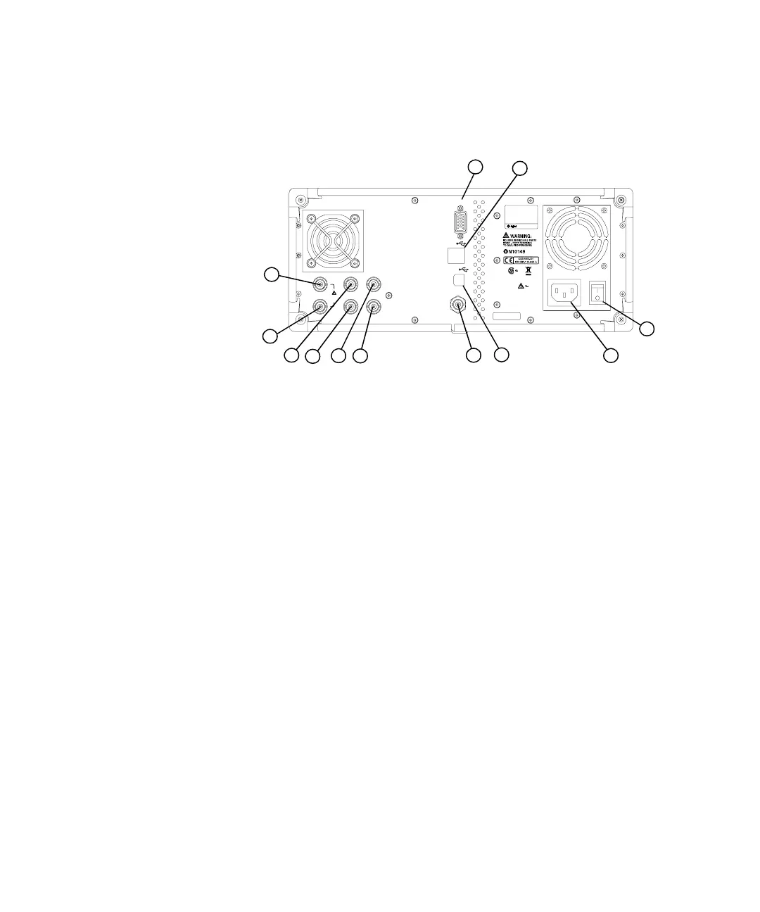
Rear Panel Overview
1Power switchThe power switch isolates the signal generator
from the AC line power. After switching on this switch, the
signal generator enters into standby and the orange standby
LED on the front panel is turned on.
2 AC power receptacle The power receptacle accepts a three- pin
plug.
3 USB Host connector Used for connecting with a controller,
such as a PC.
4 TRIG IN connector Female BNC connector, accepts a TTL
signal for triggering an sweep. Triggering occurs on either
the positive or negative edge. The frequency of the external
trigger source is no greater than 100 Hz. The damage level is
+10 V or –4 V.
5 REF OUT connector Female BNC connector is for a output of
the internal reference frequency, which has a nominal output
level greater than 0.35Vrms, and an output impedance of 50
ohm.
VGA OUTPUT
DEV
TRIG IN
HOST
MOD IN
PULSE M OD I N
REF IN
REF OUT
I IN
1V RMS
MAX
Q IN
LIN E:
100-240V
50-60Hz
100W M AX
Made in China
HIPOT PAS S
N931 0A N93 10A-CFG00 2
SER:CN** ****** *
1
3
4
6
7
8
9
10
11
12
2
5
≥≤

 Loading...