46 N9310A User’s Guide
3Using Functions
Generating an I/Q Modulated Signal (Option 001 Only)
The signal generator generates I/Q modulated signals with
the following basic characters:
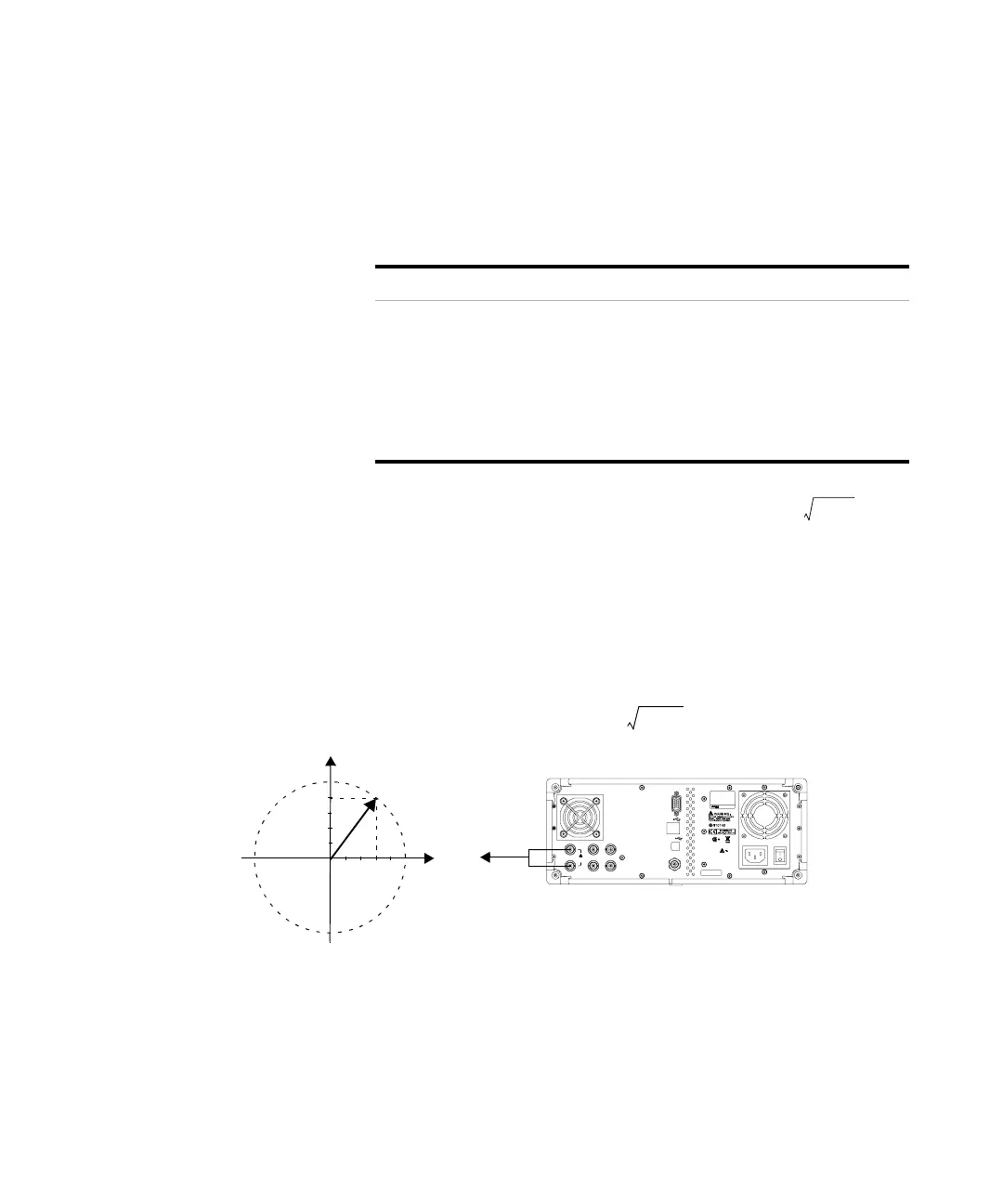
If you use a constant sum vector modulation of = 0.5
V to drive the I/Q modulator, the actual RF level
corresponds to the displayed RF level. To avoid overdriving
the I/Q modulator, you must take care that the sum vector
never exceed 0.5 V when using I/Q modulation. For full- scale
input, the peak envelope power of the modulated RF signal
is thus equal to the indicated LEVEL. The average power is
smaller.
Character Range Default
I/Q Source External source only N/A
I/Q Input 50 W impedance
VSWR < 1.5
Full scale input < 0.5 Vrms
N/A
I/Q Input Connector EXT I and Q connector on
rear panel (BNC type, female)
N/A
I
2
Q
2
+
Q
I
VGA OUTPUT
DEV
TRIG IN
HOST
MOD IN
PULSE MOD IN
REF IN
REF O UT
I IN
1V RMS
MAX
Q IN
LIN E:
100-240V
50-60Hz
100W M AX
Mad e in Chin a
HI POT PA SS
N9310A N 9310A -CFG002
SER:CN*********
Amplitude = input value LEVEL
I
2
Q
2
+
0.5V
---------------------