Service Guide E8361-90001 4-43
PNA Series Microwave Network Analyzers Troubleshooting
E8361A Measurement System Troubleshooting
4. If the signal is present, reconnect cable W1 to A12 and then continue with “Checking
the A21 Output, All Bands” on page 4-43.
Checking the A21 Output, All Bands
1. Disconnect W2 from A21.
2. Connect a cable to A21 and measure the output power. A power level of −7 dBm ±5dB
indicates the A21 assembly is functioning normally.
3. If the output power level, is at or below the minimum power level for the power sensor,
replace the A21 assembly.
4. If the signal is present, reconnect cable W2 to A21 and then continue with “Checking
the A23 and A24 Output, All Bands” on page 4-43.
Checking the A23 and A24 Output, All Bands
• Perform this procedure if the test port output power is low on one port and not on the
other.
1. Disconnect the three semi-rigid cables, one flex cable, and one ribbon cable from each of
the A23 and A24 SOMA 70 assemblies.
2. Swap the A23 and A24 assemblies.
3. Reconnect all cables.
4. Measure the test port power again.
5. If the problem follows the SOMA 70, replace the faulty assembly.
6. If the problem does not follow the SOMA 70, recheck all cable connections and the A25
and A26 coupler assemblies associated with the SOMA 70 assemblies (refer to
“Checking the Signal Separation Group” on page 4-49).
Checking the A10 5 MHz Reference Output, All Bands
1. Refer to the block diagram at the end of this chapter and to “Top Cables, All Options
Except 080” on page 6-14. Locate flexible cable W43, at the A10 frequency reference
board.
2. Disconnect W43 from A10J10.
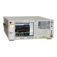
3. Connect the spectrum analyzer to A10J10.
4. The spectrum analyzer should measure a signal at 5 MHz.
5. If no 5 MHz signal is present, replace the A10 frequency reference board. Refer to
“Removing and Replacing the A6, A8, A9, and A10 Boards” on page 7-18.
6. If the 5 MHz signal is present, reconnect cable W43, and then continue with “Checking
the A10 Phase Lock Reference Output, All Bands” on page 4-44.

 Loading...


