Service Guide E8361-90001 5-19
PNA Series Microwave Network Analyzers Theory of Operation
E8361A Signal Separation Group Operation
High Dynamic Range Configuration
With a few jumper changes, you can configure the Option 014 for higher dynamic range
measurements. By swapping the front panel jumpers for one port, signal flow through the
corresponding coupler is reversed, increasing the test signal sensitivity by 15 dB.
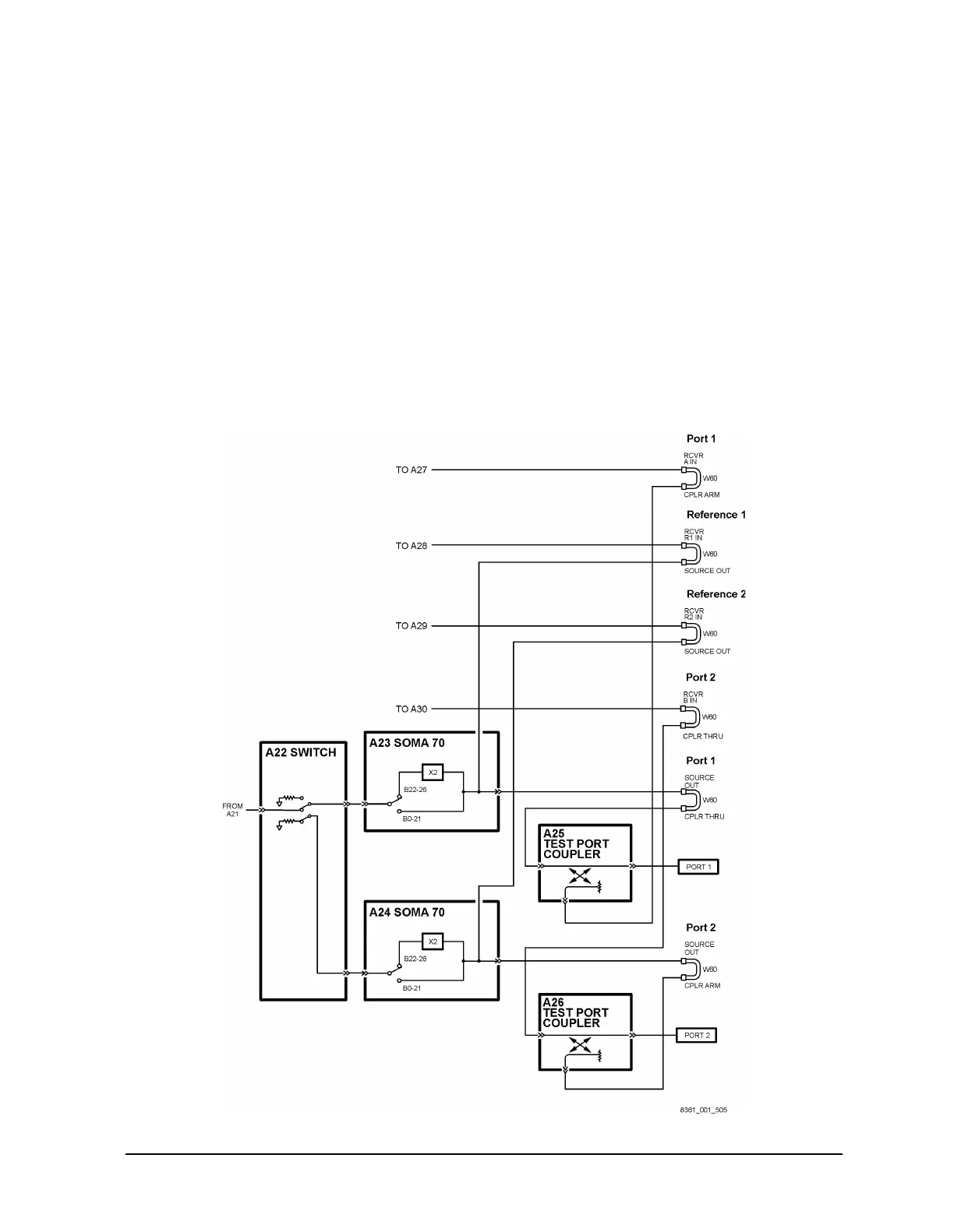
In the forward direction, as shown in Figure 5-5, the signal flow through the test port
coupler (A26) is reversed by arranging the front panel jumpers such that RCVR B IN
connects to CPLR THRU and CPLR ARM connects to SOURCE OUT.
In the reverse direction, not shown, the signal flow through the test port coupler (A25) is
reversed by arranging the front panel jumpers such that RCVR A IN connects to
CPLR THRU and CPLR ARM connects to SOURCE OUT.
For more information on high dynamic range measurements and configurations, search for
“Option 014” in the embedded help index in the analyzer.
Figure 5-5 High Dynamic Range Configuration in the Forward Direction
 Loading...


