Service Guide E8361-90001 4-11
PNA Series Microwave Network Analyzers Troubleshooting
E8361A Power Up Troubleshooting
To further isolate the failure in the three remaining assemblies, measure the resistance on
the extender board (with the power turned off) from the power supply test points to “GND”.
Refer to Figure 4-3 on page 4-9. The voltages should be as shown in Table 4-2.
NOTE Make sure that the only assemblies plugged in are the three minimum
required assemblies listed above.
Check for shorts (zero Ω) or very low resistance (approximately 1 Ω). If a short or low
resistance is measured, isolate each of the remaining three boards in the following order,
and recheck the shorted test point after each board is removed. Note that the resistance
may be different from that listed in the table, but you should be able to determine if the
shorted condition has changed.
Isolate the remaining three assemblies:
• remove the A15 CPU board
• remove the A4 power supply
• This leaves only the A14 system motherboard installed. If the measurements are still
incorrect, this is the suspected faulty assembly.
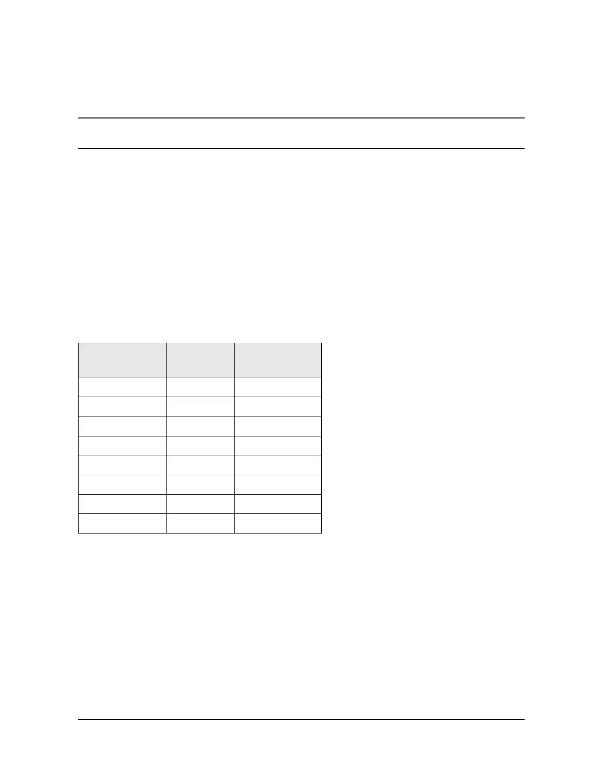
Table 4-2 Power Supply Voltages and Resistances
Measurement
Location
Supply
(Vdc)
Approximate
Resistance (Ω)
A +5.0 285
B −15.0 12.7 k
C −5.0 7.2 k
D +9 4.0 k
E +15 3.0 k
F +22 2.8 k
G+22890
H +32 2.6 k
 Loading...


