4-16 Service Guide E8361-90001
Troubleshooting PNA Series Microwave Network Analyzers
Power Up Troubleshooting E8361A
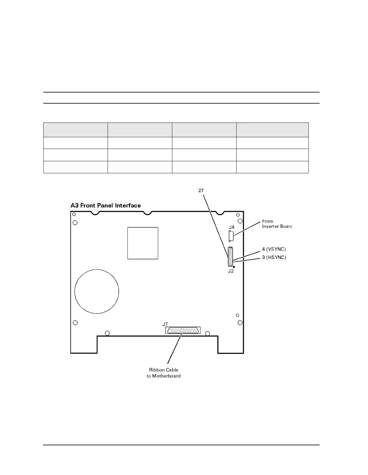
Verifying the A3 Front Panel Interface Board
To verify that the HSYNC (horizontal sync), VSYNC (vertical sync), and LCD clock are
functioning correctly, measure the signals listed in Table 4-5 and illustrated in Figure 4-6
on page 4-16. If all of these signals measure correctly, suspect a defective backlight or LCD.
The backlight is the most probable cause.
CAUTION Be careful not to short connector pins together when measuring these signals.
Figure 4-6 Verifying HSYNC, VSYNC, and LCD Clock
If any of the three signal types is incorrect, replace the A3 front panel interface board.
Refer to “Removing the A3 Front Panel Interface Board” on page 7-12.
If all of the signal types are correct, replace the A2 display assembly. Refer to “Removing
the A2 Display Assembly” on page 7-12.
Table 4-5 A3 Front Panel Interface Board, Voltages and Signals
Signal Type Test Point Voltage Signal
HSYNC J2 pin 3 0 to +3 V 30.8 kHz square wave
VSYNC J2 pin 4 0 to +3 V 60 Hz square wave
CLOCK J2 pin 27 0 to +3.4 V pk-to-pk 25 MHz sine wave
 Loading...


