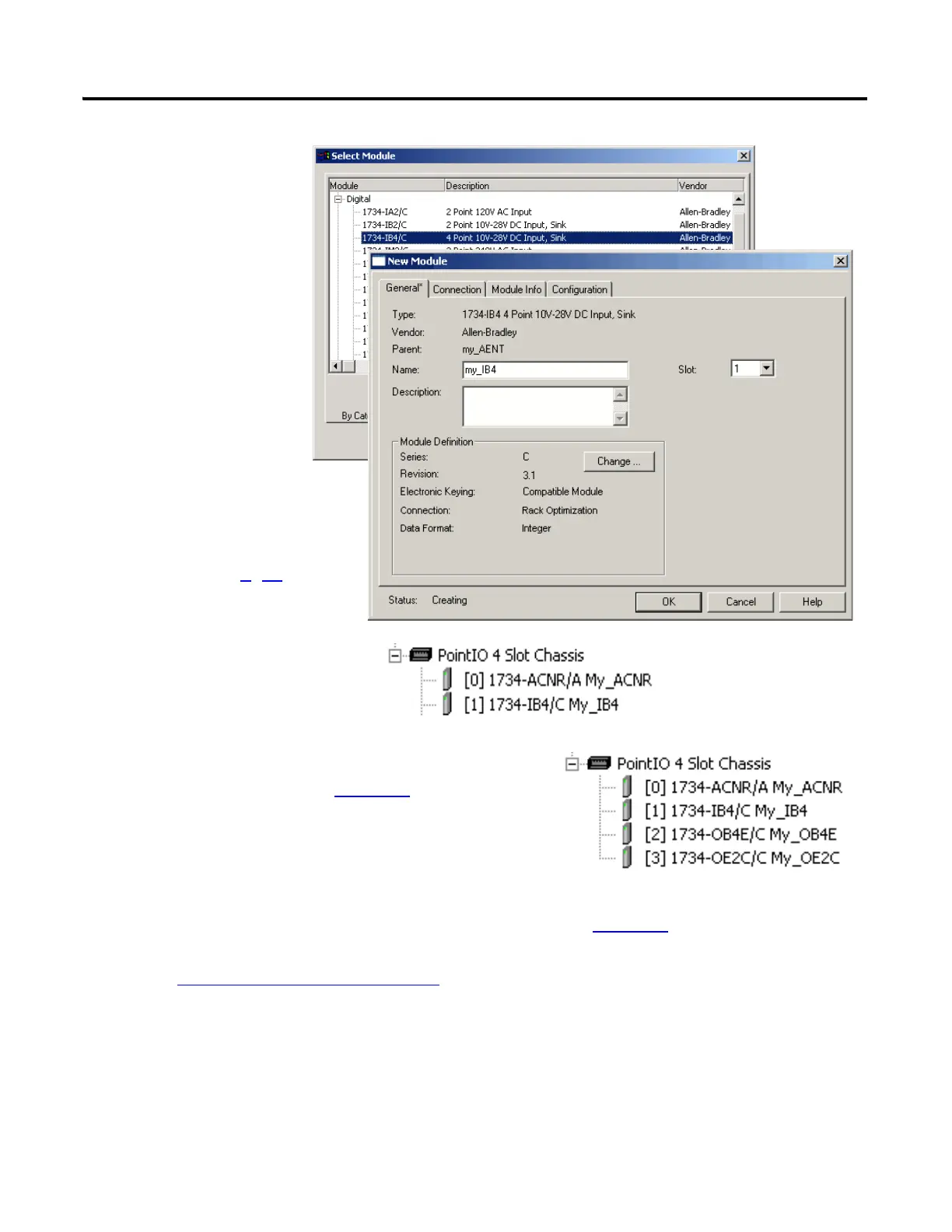
EasyManuals Logo

Allen-Bradley CompactLogix Series User Manual

Allen-Bradley CompactLogix Series
218 pages
To Next Page IconTo Next Page
To Previous Page IconTo Previous Page
Page #117 background imageLoading...
Page #117 background image
Publication IASIMP-QS001C-EN-P - October 2009 117
Add Distributed I/O Modules to the Project Chapter 11
11. Enter a name.
12. Click OK.
The module is added to the
I/O Configuration.
13. Repeat steps 9
12 until all
of your distributed I/O
modules are added in order
from left to right.
10. Select the left-most
POINT I/O module
in your chassis and
click OK.
ControlNet
Shown
If you have added more than one digital output module, select the one you want to test
in this project and record the name and slot number on page 128
.
Go to Add Ladder Logic
on page 127.
14. Record the adapter name and digital output
module slot number on page 128
.

Table of Contents

Questions and Answers:

Question and Answer IconNeed help?

Do you have a question about the Allen-Bradley CompactLogix Series and is the answer not in the manual?

Allen-Bradley CompactLogix Series Specifications

General IconGeneral
Communication PortsEtherNet/IP
Programming SoftwareStudio 5000 Logix Designer
Power Supply24V DC
SeriesCompactLogix
Programming LanguagesLadder Diagram (LD), Structured Text (ST), Function Block Diagram (FBD), Sequential Function Chart (SFC)
Operating Temperature0°C to 60°C (32°F to 140°F)
MountingDIN rail
Processor TypeVarious (depends on model)

Related product manuals