12 Rockwell Automation Publication 20B-IN026C-EN-P - October 2015
Preface
Safety Precautions
Follow all the precautions and general installation requirements provided in the
PowerFlex 700 Frame 7-10 Installation Instructions (publication 20B-IN014
)
and the PowerFlex 700 User Manual (publication 20B-UM002
) along with those
included here.
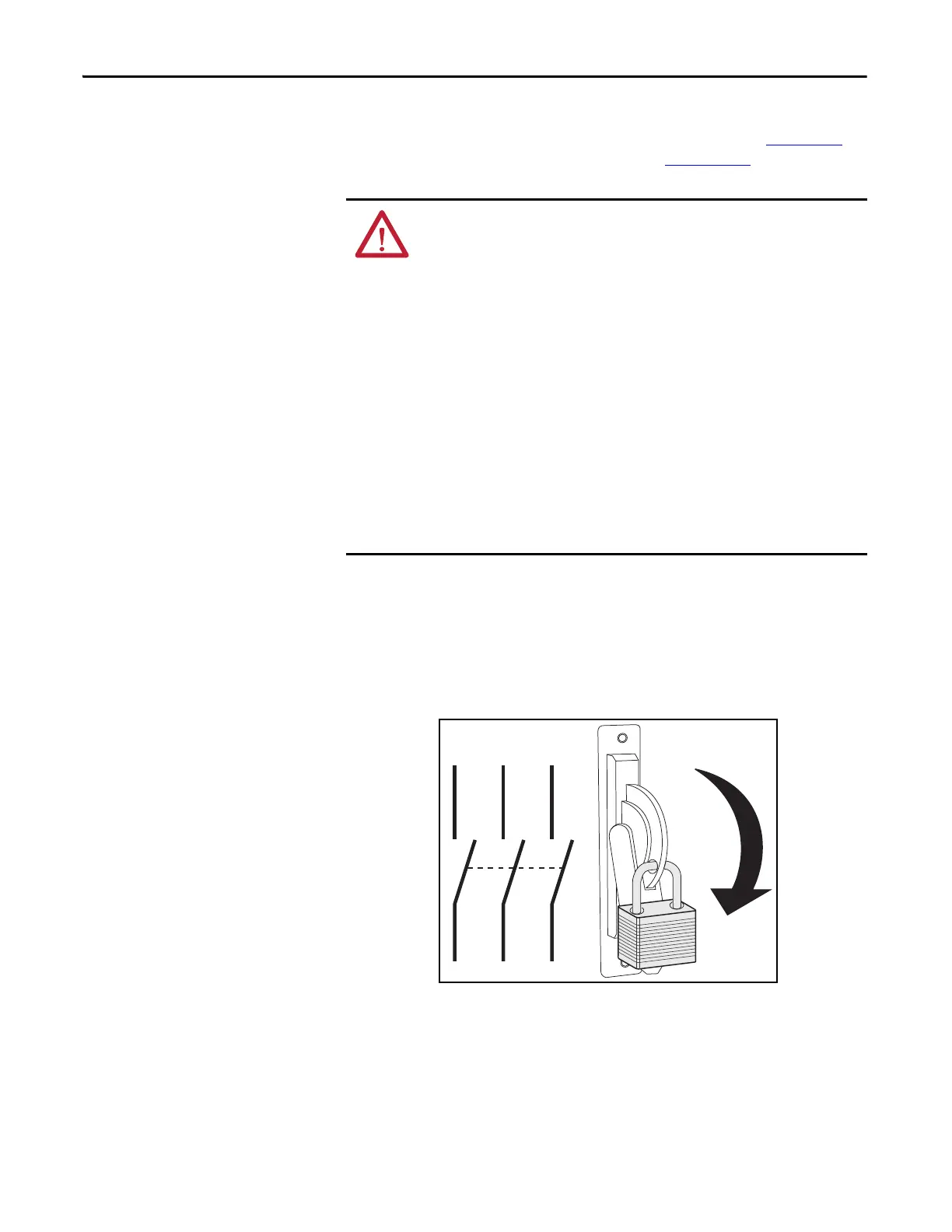
1. Turn off and lock out input power. Wait five minutes.
2. Verify that there is no voltage at the drive’s input power terminals.
3. Check the DC bus voltage at the Power Terminals by measuring between
the +DC and –DC terminals, between the +DC terminal and the chassis,
and between the –DC terminal and the chassis. The voltage must be zero
for all three measurements.
ATTENTION: To avoid an electric shock hazard, ensure that all power has
been removed before proceeding. In addition, before servicing, verify
that the voltage on the bus capacitors has discharged. Check the DC bus
voltage at the Power Terminals by measuring between the +DC and -DC
terminals, between the +DC terminal and the chassis, and between the
-DC terminal and the chassis. The voltage must be zero for all three
measurements.
Remove power before making or breaking cable connections. When you
remove or insert a cable connector with power applied, an electrical arc
may occur. An electrical arc can cause personal injury or property damage
by:
• sending an erroneous signal to your system’s field devices, causing
unintended machine motion.
• causing an explosion in a hazardous environment.
Electrical arcing causes excessive wear to contacts on the module and its
mating connector. Worn contacts may create electrical resistance.
L1 L2 L3
O
I

 Loading...


