Rockwell Automation Publication 20B-IN026C-EN-P - October 2015 67
Inverter Assembly Component Replacement Procedures Chapter 3
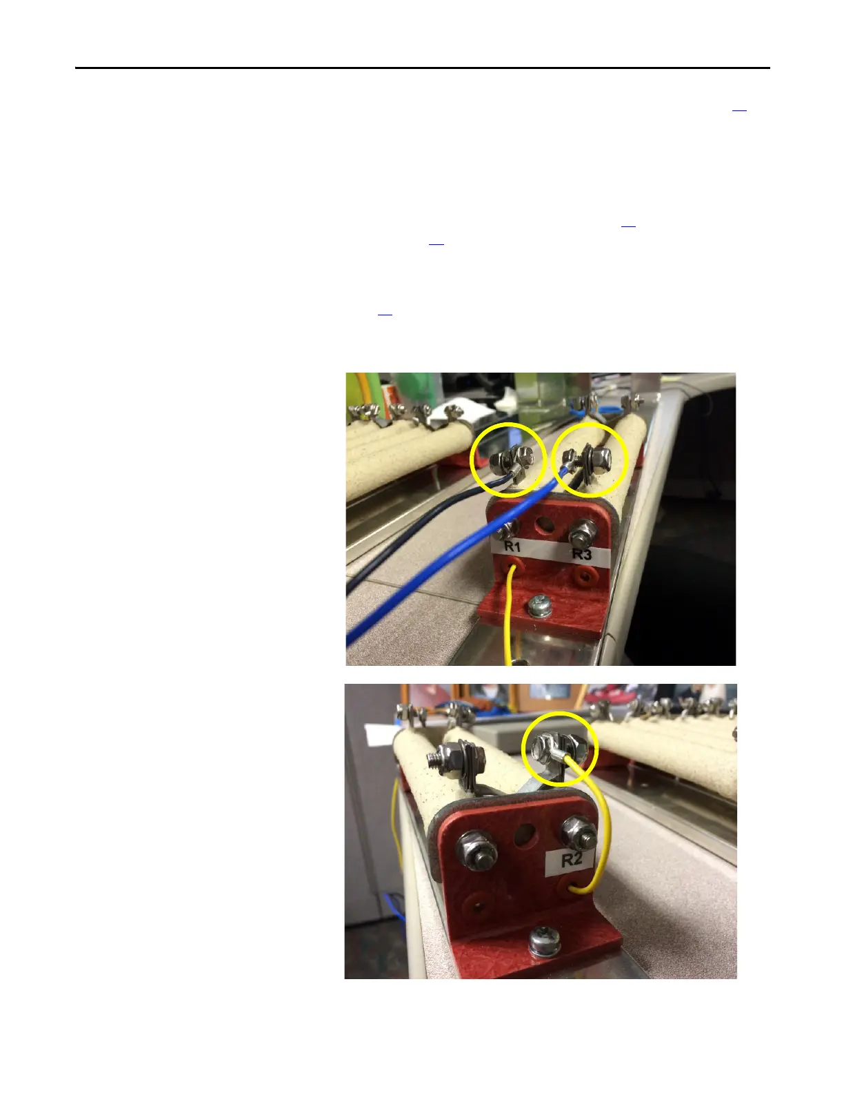
Balancing Resistor
See Chapter 1 - Component Diagrams and Torque Specifications on page 15 to
locate components in these instructions.
Remove Components
1. Read and follow the Safety Precautions on page 12 and Important Initial
Steps on page 13
.
2. Remove safety shields and enclosure covers as needed.
3. Remove the Stacking Panel. See Stacking Panel (Inverter Assembly) on
page 26
.
4. Verify the rating of the resistors to be sure there was no damaged during
shipment (R1 to R2 = R2 to R3 = 6.8 kΩ ±5%).

 Loading...


