50 Rockwell Automation Publication 20B-IN026C-EN-P - October 2015
Chapter 3 Inverter Assembly Component Replacement Procedures
DC Bus Filter Board
See Chapter 1 - Component Diagrams and Torque Specifications on page 15 to
locate components in these instructions.
Remove Components
1. Read and follow the Safety Precautions on page 12 and Important Initial
Steps on page 13
.
2. Remove safety shields and enclosure covers as needed.
3. Remove the safety shield over the DC Bus Filter Board.
4. Carefully label and disconnect all wiring from TB1 and TB2 terminals.
5. Remove the board mounting bolts (4).
6. Remove the DC Bus Filter Board; return or dispose of it properly.
Install Components
1. Install the new DC Bus Filter Board. Torque mounting bolts to 1.8 N•m
(16 lb•in).
2. Reconnect all wiring as detailed in the above Table.
3. Replace all safety shields and enclosure covers before applying power to the
drive.
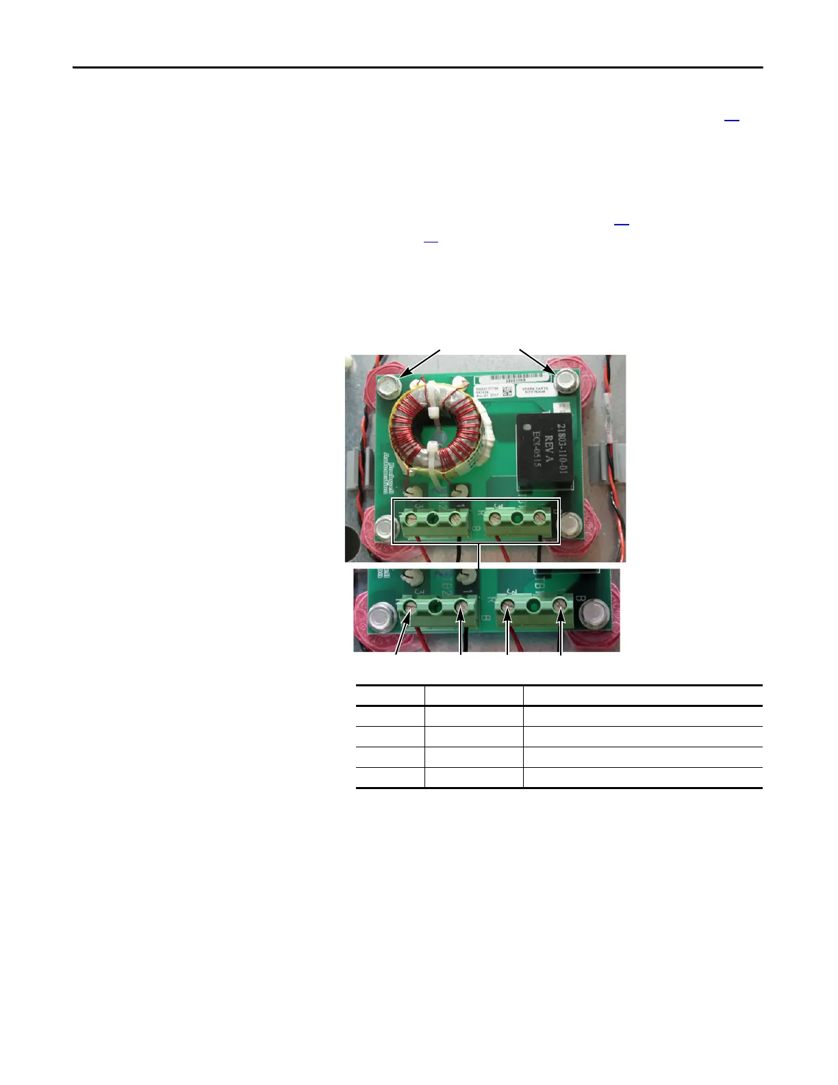
TB2 TB1
TB2-3 TB2-1 TB1-3 TB1-1
Board Mounting Bolts (4)
Connector Wire Color(s) Connects To:
TB1-1 Black J24 on Power Interface Board
TB1-3 Red J24 on Power Interface Board
TB2-1 Black DC- Bus Capacitor
TB2-3 Red DC+ Bus Capacitor

 Loading...


