42 Rockwell Automation Publication 20B-IN026C-EN-P - October 2015
Chapter 3 Inverter Assembly Component Replacement Procedures
T-Comm Board
See Chapter 1 - Component Diagrams and Torque Specifications on page 15 to
locate components in these instructions.
Remove Components
1. Read and follow the Safety Precautions on page 12 and Important Initial
Steps on page 13
.
2. Remove safety shields and enclosure covers as needed.
3. Remove the HIM Cradle/Board:
a. Remove the HIM Module from its slot (if used).
b. Disconnect the ribbon cable from the HIM Cradle/Board (connects to
J3 on the Main Control Board).
c. Disconnect the wiring connector from the HIM Cradle/Board
(connects to 8-pin serial port in the lower-right corner of Main Control
Board panel).
d. Remove and save the grounding-wire screw (connects to PE on TB11).
e. Remove and save the two mounting screws for the HIM Cradle/Board.
f. Remove the HIM Cradle/Board.
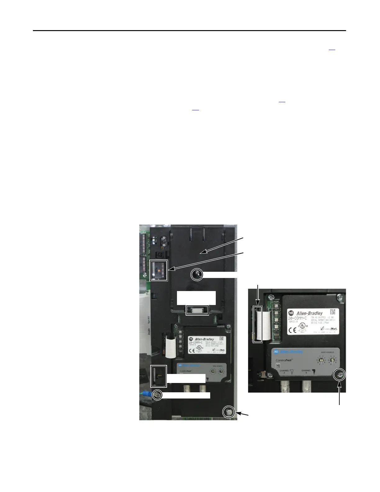
HIM Module slot
Mounting Screw
Optional 20-COMM-C Board Detail
Ribbon Cable Connector
Grounding-Wire Screw
Ribbon Cable Connector to
T-Comm Board
Mounting Screws (4)
Mounting Screw
HIM Module
Connector
Wiring Connector

 Loading...


