Rockwell Automation Publication 20B-IN026C-EN-P - October 2015 53
Inverter Assembly Component Replacement Procedures Chapter 3
Capacitor Bank Fan
See Chapter 1 - Component Diagrams and Torque Specifications on page 15 to
locate components in these instructions.
Remove Components
1. Read and follow the Safety Precautions on page 12 and Important Initial
Steps on page 13
.
2. Remove safety shields and enclosure covers as needed.
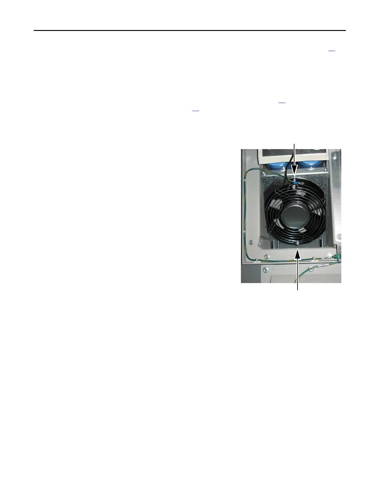
3. Locate the Capacitor Bank
Fan at the bottom of the
Capacitor bank.
4. Label and disconnect all wires
for the fan.
5. Remove the top and bottom
mounting screws.
6. Remove the fan assembly and
dispose of it properly.
Install Components
1. Install the fan assembly and
torque the two mounting
screws to 1.8 N•m (16 lb•in).
2. Reconnect the wires.
3. Replace all safety shields and
enclosure covers before
applying power to the drive.
Top Mounting Screw
(behind the fan guard screw).
Bottom Mounting Screw
(behind the fan guard screw).

 Loading...


