EasyManuals Logo

Allen-Bradley powerflex 700 Installation Instructions

Allen-Bradley powerflex 700
96 pages
To Next Page IconTo Next Page
To Previous Page IconTo Previous Page
Page #86 background imageLoading...
Page #86 background image
86 Rockwell Automation Publication 20B-IN026C-EN-P - October 2015
Chapter 4 Converter Assembly Component Replacement Procedures
Snubber Boards
See Chapter 1 - Component Diagrams and Torque Specifications on page 15 to
locate components in these instructions.
Remove Components
1. Read and follow the Safety Precautions on page 12 and Important Initial
Steps on page 13
.
2. Remove safety shields and enclosure covers as needed.
3. Locate the Snubber Board(s) to be replaced.
4. Carefully label and disconnect the wires from Snubber Board(s) that will
be replaced.
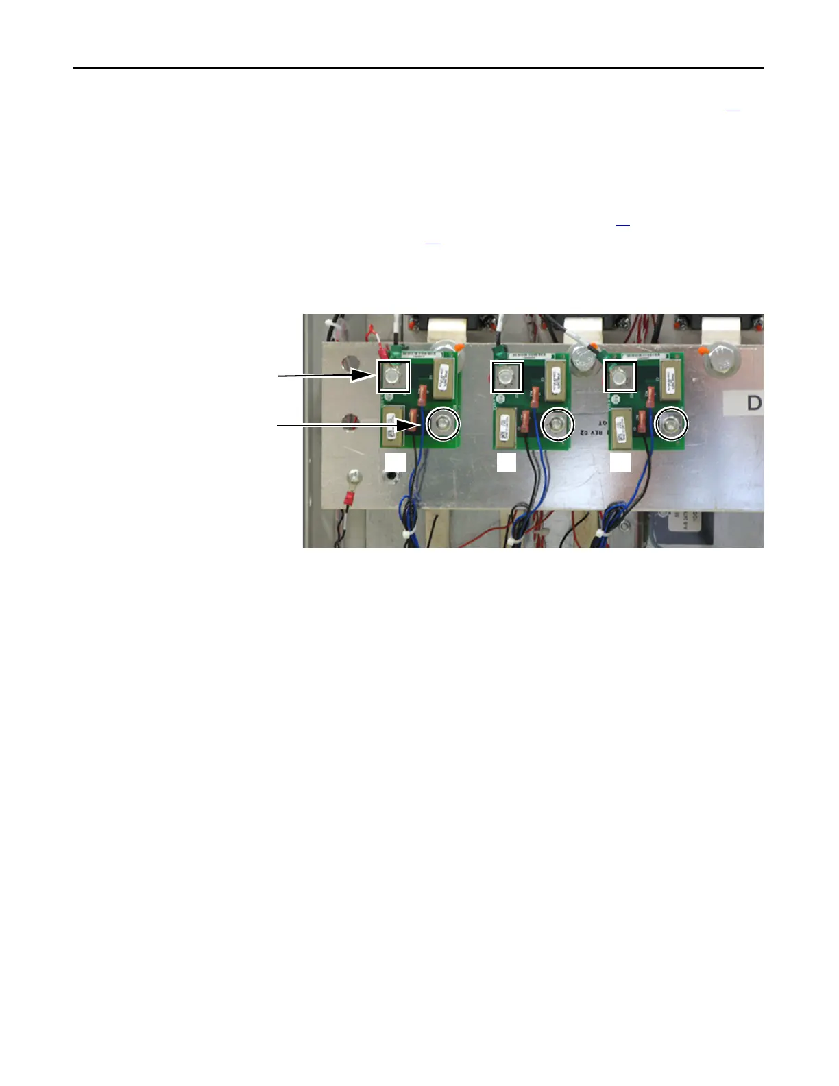
5. Remove the DC1 terminal screw and mounting screw for the Snubber
Board(s) to be replaced.
6. Remove the Snubber Board(s) and properly discard.
R
S
T
DC1 Terminal Screw
Mounting Screw

Table of Contents

Other manuals for Allen-Bradley powerflex 700

Questions and Answers:

Question and Answer IconNeed help?

Do you have a question about the Allen-Bradley powerflex 700 and is the answer not in the manual?

Allen-Bradley powerflex 700 Specifications

General IconGeneral
SeriesPowerFlex 700
CategoryAC Drive
Input Voltage200-240V AC, 380-480V AC, 500-600V AC
EnclosureType 1
Control MethodSensorless Vector
CommunicationEtherNet/IP, ControlNet, DeviceNet, PROFIBUS DP, Modbus

Related product manuals