Rockwell Automation Publication 20B-IN026C-EN-P - October 2015 79
Converter Assembly Component Replacement Procedures Chapter 4
MOV Surge Suppressor
See Chapter 1 - Component Diagrams and Torque Specifications on page 15 to
locate components in these instructions.
Remove Components
1. Read and follow the Safety Precautions on page 12 and Important Initial
Steps on page 13
.
2. Remove safety shields and enclosure covers as needed.
3. Locate the MOV Surge Suppressor assembly.
4. Remove the MOV enclosure cover (2 nuts).
5. Note wire placement and connections. Disconnect the MOV ground wire
to transformer.
6. Carefully label and disconnect the R, S, and T MOV wires to the AC
Busbars.
7. Remove the MOV mounting nut.
8. Remove the MOV assembly and properly discard.
Install Components
1. Install the new MOV assembly. Torque the MOV mounting nut to
2.9 N•m (26 lb•in).
2. Reconnect all wires and connectors for the MOV.
3. Torque the R, S, and T MOV wires to the AC Busbars to 2.9 N•m
(26 lb•in).
4. Reassemble remaining components in reverse order.
5. Replace all safety shields and enclosure covers before applying power to the
drive.
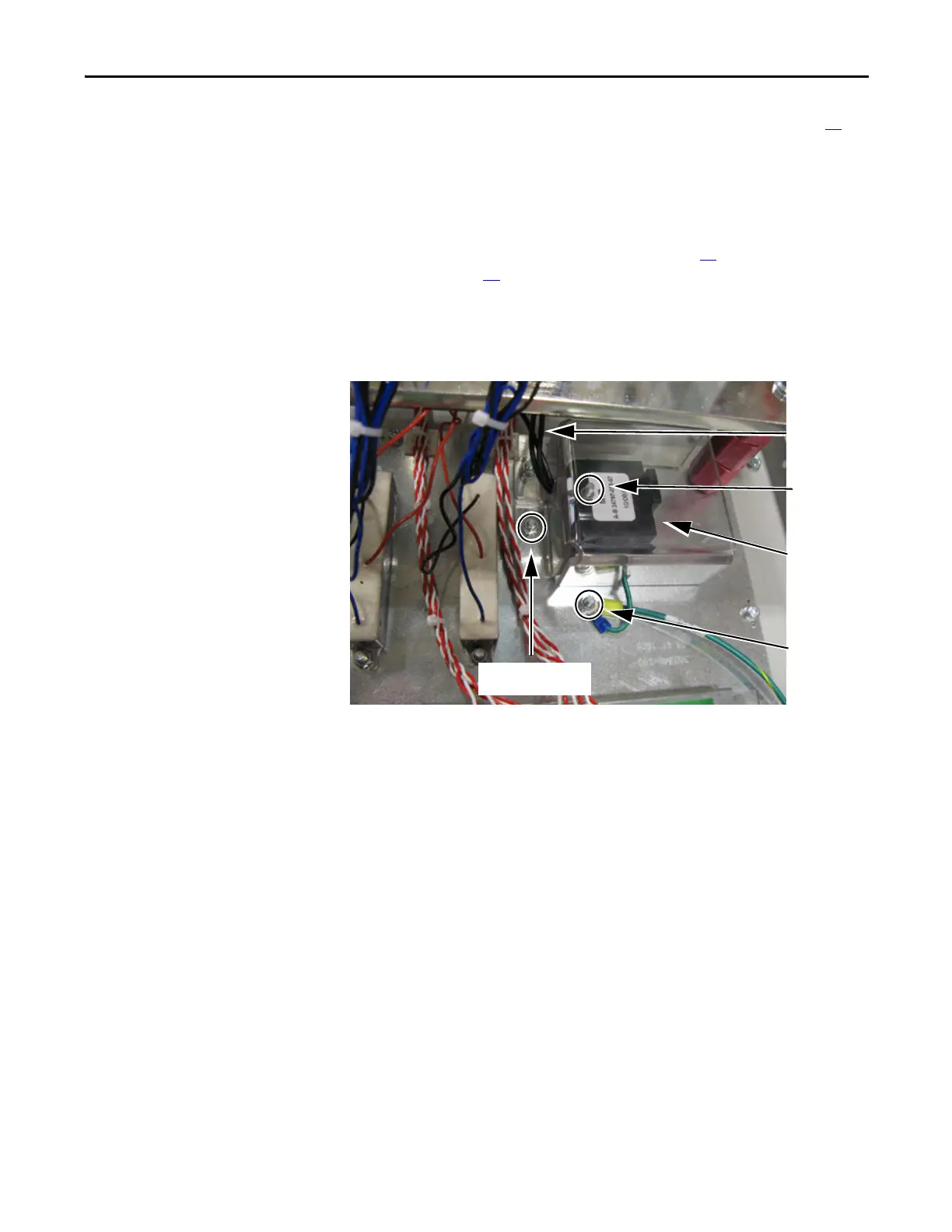
MOV Surge
Suppressor
MOV
Mounting Nut
MOV Ground
Wire
MOV Enclosure Cover Nuts
(2)
R, S, and T
MOV Wires

 Loading...


