Rockwell Automation Publication 20B-IN026C-EN-P - October 2015 55
Inverter Assembly Component Replacement Procedures Chapter 3
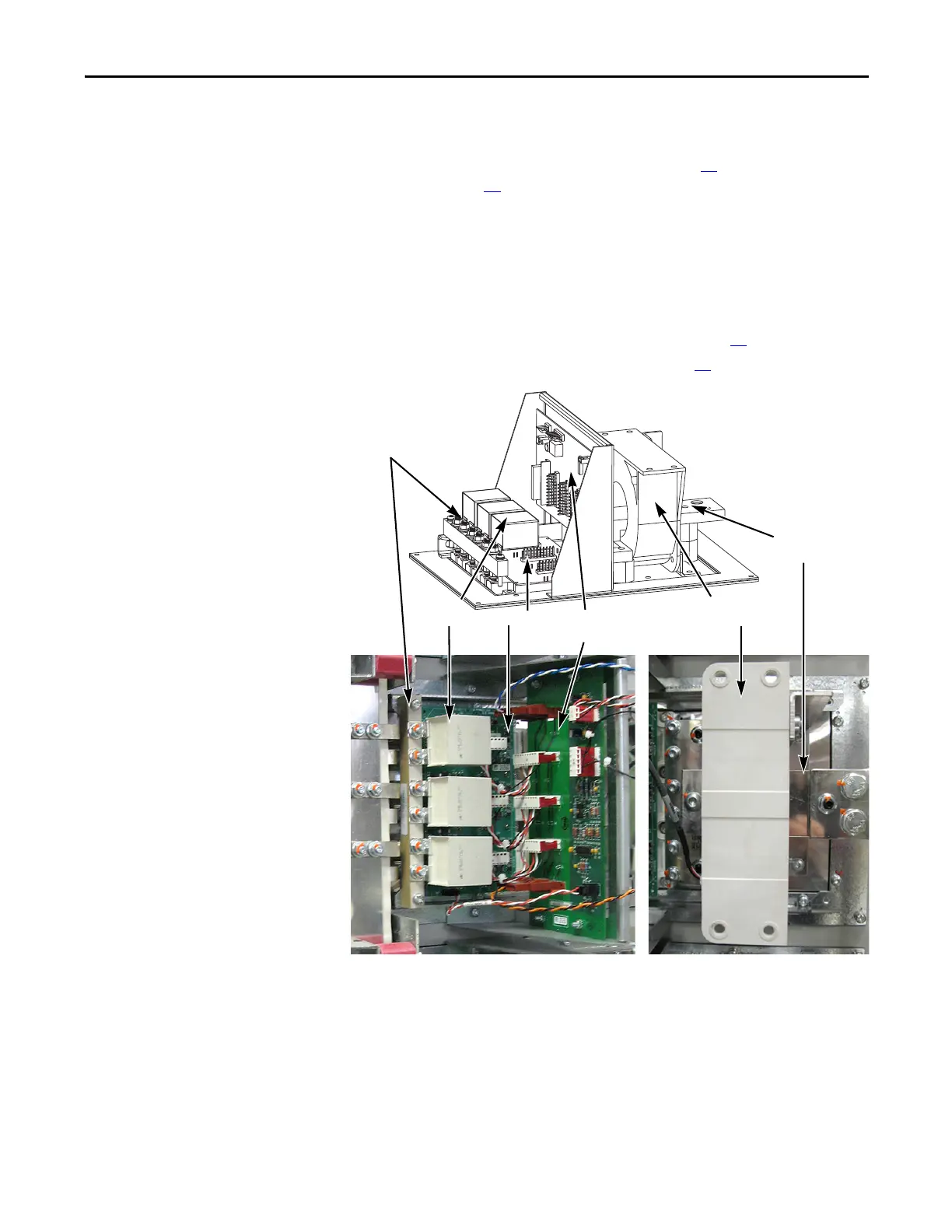
Remove Components
1. Read and follow the Safety Precautions on page 12 and Important Initial
Steps on page 13
.
2. Remove safety shields and enclosure covers as needed.
3. Locate the Inverter Power Module (IGBT Module) to be replaced.
4. If you are replacing the lower IGBT Module, it may be easier if you remove
the Main Control Panel and Stacking Panel. If you need to remove the
panels, remove them in this order:
a. Main Control Panel (Inverter Assembly) on page 24
.
b. Stacking Panel (Inverter Assembly) on page 26
.
Gate Interface
Board Assembly
Tie Down Capacitor
Mount
Snubber
Capacitors
AC Output
Busbar
Current
Transd ucer
IGBT Module

 Loading...


