56 Rockwell Automation Publication 20B-IN026C-EN-P - October 2015
Chapter 3 Inverter Assembly Component Replacement Procedures
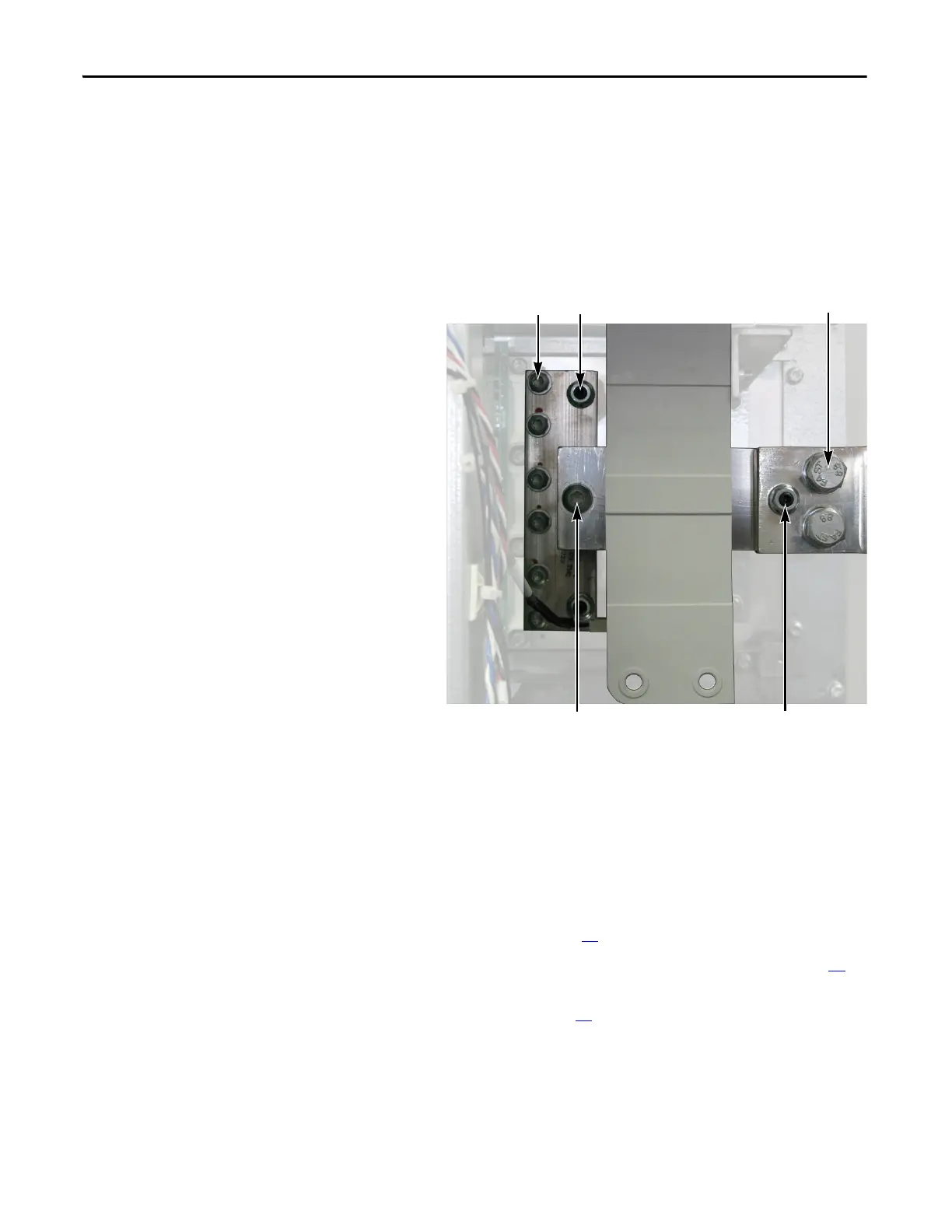
5. Remove the Output Busbar at the Current Transducer:
a. Remove and save the torx head bolt that secures the Output Busbar to
the AC Output Busbar.
b. Remove and save the two hex head bolts that secure the Output Busbar
to the U, V, or W Busbar.
c. Remove and save the nut and set screw for the Output Busbar standoff.
d. Slide the Output Busbar to the right as far as it goes.
6. Remove the AC Output Busbar:
a. Remove and save the six torx screws and two standoff nuts that secure
the AC Output Busbar to the IGBT module.
b. Remove and save the two nuts that secure the AC Output Busbar to the
standoffs.
c. Remove and save the AC Output Busbar.
7. Remove all IGBT Snubber components. See Remove all IGBT Snubber
components (3 sets): on page 30
.
8. Remove the Gate Interface Board. See Gate Interface Board on page 60
.
9. Remove the Transitional Busbar (See Transitional Busbar Assembly
(Inverter Assembly) on page 29
) if Bus Capacitors or the positive (DC+)
Flexible Capacitor Busbars supplied with the kit must be installed.
10. Remove the eight screws that secure the IGBT module to the chassis.
Remove the IGBT module by tipping the right edge out first; return or
dispose of it properly.
AC Output Busbar Torx
Screws (6)
Output Busbar Torx
Head Bolt
AC Output Busbar
Standoff Nuts (2)
Output Busbar Standoff Nut
and Set Screw
Output Busbar
Hex Head Bolts(2)

 Loading...


