Rockwell Automation Publication 20B-IN026C-EN-P - October 2015 83
Converter Assembly Component Replacement Procedures Chapter 4
Precharge Board
See Chapter 1 - Component Diagrams and Torque Specifications on page 15 to
locate components in these instructions.
Remove Components
1. Read and follow the Safety Precautions on page 12 and Important Initial
Steps on page 13
.
2. Remove safety shields and enclosure covers as needed.
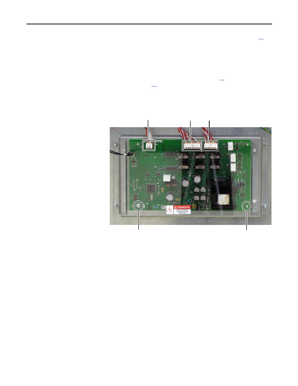
3. Carefully label and disconnect all wiring plugs from the Precharge Board.
4. Remove the Precharge Board mounting torx screw (1) located at the lower
left corner of the Precharge Board.
5. Use your fingers or needle-nose pliers to squeeze the tabs of each of the
three spacers and separate the Precharge Board from the mounting plate.
6. Remove the Precharge Board; return or dispose of it properly.
Install Components
1. Install the new Precharge Board.
2. Torque the Precharge Board mounting screw to 1.8 N•m (16 lb•in).
3. Reconnect all wiring plugs as shown in the figure on the previous page.
4. Replace all safety shields and enclosure covers before applying power to the
drive.
Spacers (3)Mounting Screw (1)
J3J1 J2

 Loading...


