Rockwell Automation Publication 20B-IN026C-EN-P - October 2015 41
Inverter Assembly Component Replacement Procedures Chapter 3
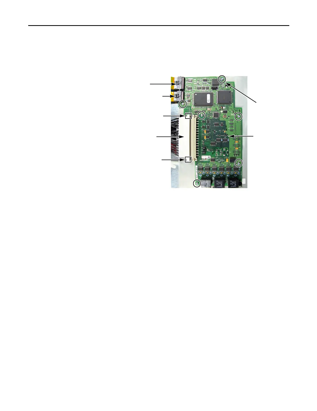
7. Disconnect the ribbon cable that connects the Main Control Board to the
Power Interface Board.
8. Loosen the two connector screws for the TB11 Harness Connector on the
Main Control Board.
9. Gently pull to disconnect the TB11 Harness Connector from the Main
Control Board.
Do not disconnect any Harness Connector wires from TB11.
10. If present, unscrew the two screws for the Encoder Board. Gently pull off
the Encoder Board.
11. Unscrew the six screws and two hex standoffs (if Encoder Board is present)
holding the Main Control Board.
12. If present, disconnect the J7 connectors for the Encoder Board.
13. Remove the Encoder Board and put aside to reinstall later.
14. Remove the Main Control Board; return or dispose of it properly.
Install Components
1. Install the new Main Control Board with six screws and two hex standoffs
(if Encoder Board is present).
2. If present, reinstall the Encoder Board with two screws, taking care to
match the J7 connectors.
3. Torque screws on Main Control Board and Encoder Board to 0.6 N•m
(5 lb•in).
4. Reassemble all components in the reverse order of removal.
5. Reconnect all cables, safety shields and enclosure covers before applying
power to the drive.
Ribbon Cable (J2)
to Power Interface
Board (J1)
Main Control Board
Screws (6)
TB11 Harness
Connector
Main Control
Board (MCB)
Connector Screw
Connector Screw
Ribbon Cable (J3)
to T-Comm Board (J3)

 Loading...


