EasyManuals Logo

Allen-Bradley powerflex 700 Installation Instructions

Allen-Bradley powerflex 700
96 pages
To Next Page IconTo Next Page
To Previous Page IconTo Previous Page
Page #28 background imageLoading...
Page #28 background image
28 Rockwell Automation Publication 20B-IN026C-EN-P - October 2015
Chapter 2 Basic Component Removal Procedures
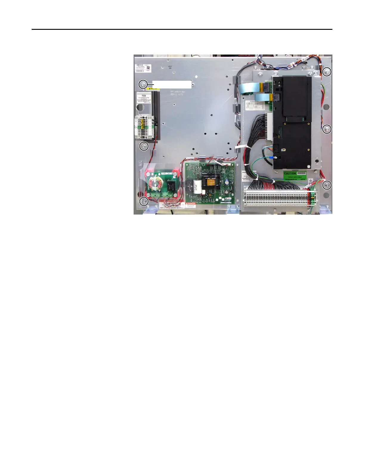
8. Remove the six nuts for mounting the Stacking Panel.
9. Remove Stacking Panel and carefully set aside.
Install Components
1. Reinstall the Stacking Panel components in the reverse order of removal.
2. Torque mounting nuts to 5.6 N•m (50 lb•in).
3. Replace all wiring to TB9.
4. Replace the black Thermal Sensor Wire to J6 on the Power Interface
Board.
5. Replace the red and black wires from TB2 on the DC Bus Filter Board.
6. Replace all safety shields and enclosure covers before applying power to the
drive.
Mounting Nuts (6)

Table of Contents

Other manuals for Allen-Bradley powerflex 700

Questions and Answers:

Question and Answer IconNeed help?

Do you have a question about the Allen-Bradley powerflex 700 and is the answer not in the manual?

Allen-Bradley powerflex 700 Specifications

General IconGeneral
SeriesPowerFlex 700
CategoryAC Drive
Input Voltage200-240V AC, 380-480V AC, 500-600V AC
EnclosureType 1
Control MethodSensorless Vector
CommunicationEtherNet/IP, ControlNet, DeviceNet, PROFIBUS DP, Modbus

Related product manuals