78 Rockwell Automation Publication 20B-IN026C-EN-P - October 2015
Chapter 4 Converter Assembly Component Replacement Procedures
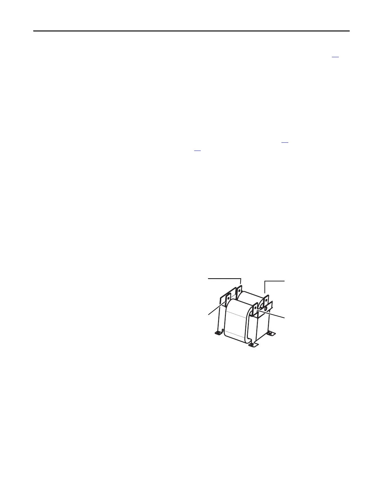
DC Link Choke
See Chapter 1 - Component Diagrams and Torque Specifications on page 15 to
locate components in these instructions.
Note: For the IP20 model, the DC Link Choke is mounted at the bottom front
of the enclosure. For the IP00 model, the DC Link Choke is supplied loose and is
mounted per installation environment (typically in a similar location as IP20).
Remove Components
1. Read and follow the Safety Precautions on page 12 and Important Initial
Steps on page 13
.
2. Remove safety shields and enclosure covers as needed.
3. Carefully label and disconnect the DC Link Choke connectors.
4. Remove the four mounting screws that mount the DC Link Choke.
5. Remove the DC Link Choke and properly discard.
Install Components
1. Install the new DC Link Choke.
2. Torque the four mounting screws to 9.0 N•m (80 lb•in).
3. Connect the DC Link Choke connectors.
4. Replace all safety shields and enclosure covers before applying power to the
drive.
+DC (Back/L2 Connector)
+DC (Back/L1 Connector)
–DC (Front/L3 Connector)
–DC (Front/L4 Connector)

 Loading...


