90 Rockwell Automation Publication 20B-IN026C-EN-P - October 2015
Chapter 4 Converter Assembly Component Replacement Procedures
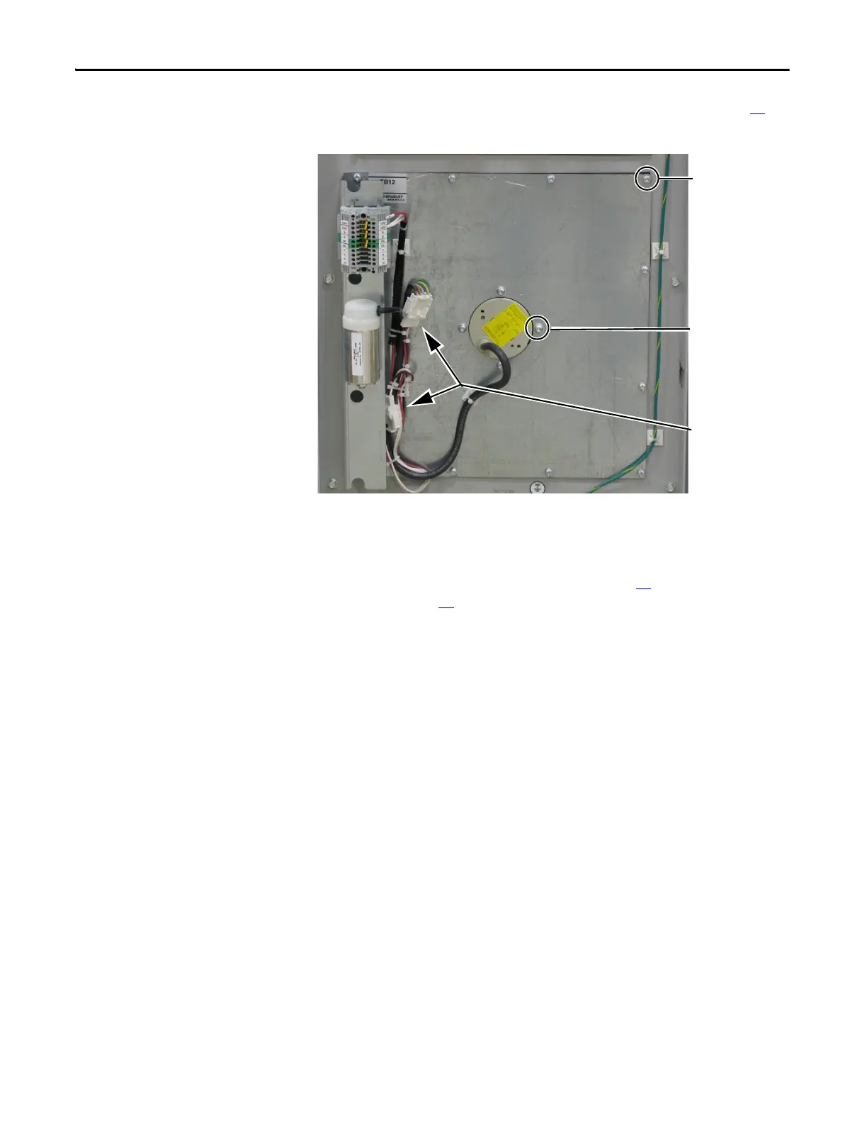
Heatsink Fan Assembly
See Chapter 1 - Component Diagrams and Torque Specifications on page 15 to
locate components in these instructions.
Remove Components
1. Read and follow the Safety Precautions on page 12 and Important Initial
Steps on page 13
.
2. Remove safety shields and enclosure covers as needed.
3. Carefully cut the plastic wire ties (do not cut the wires) and label each
connector for the Fan Capacitor or TB12.
4. Label and remove the wires from TB12 to the Transformer (120, N, PE).
5. Remove the 12 mounting bolts for the heatsink fan mounting plate.
6. Carefully remove the mounting plate and fan. You may need to pry the
mounting plate away from the gasket. Remove the gasket if damaged.
7. Remove the four heatsink fan mounting bolts and remove the heatsink fan
from the mounting plate.
Heatsink Fan
Mounting Plate Bolts
(12)
Heatsink Fan
Mounting Bolts (4)
TB12 and Fan
Capacitor Wiring
Plugs

 Loading...


